background image

69

ShopStream Connect

Scanner DataViewer

6— Main display—

shows stored data files details. 

NOTE: The files listed are sortable 

(ascending/descending) by clicking on the column tab at the top (e.g. File Name, Type, 
etc.) Sort preferences are saved when the ShopStream Connect program is closed.

7— Preview—

displays a sample of the file if the selected file is a image file. 

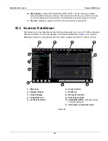
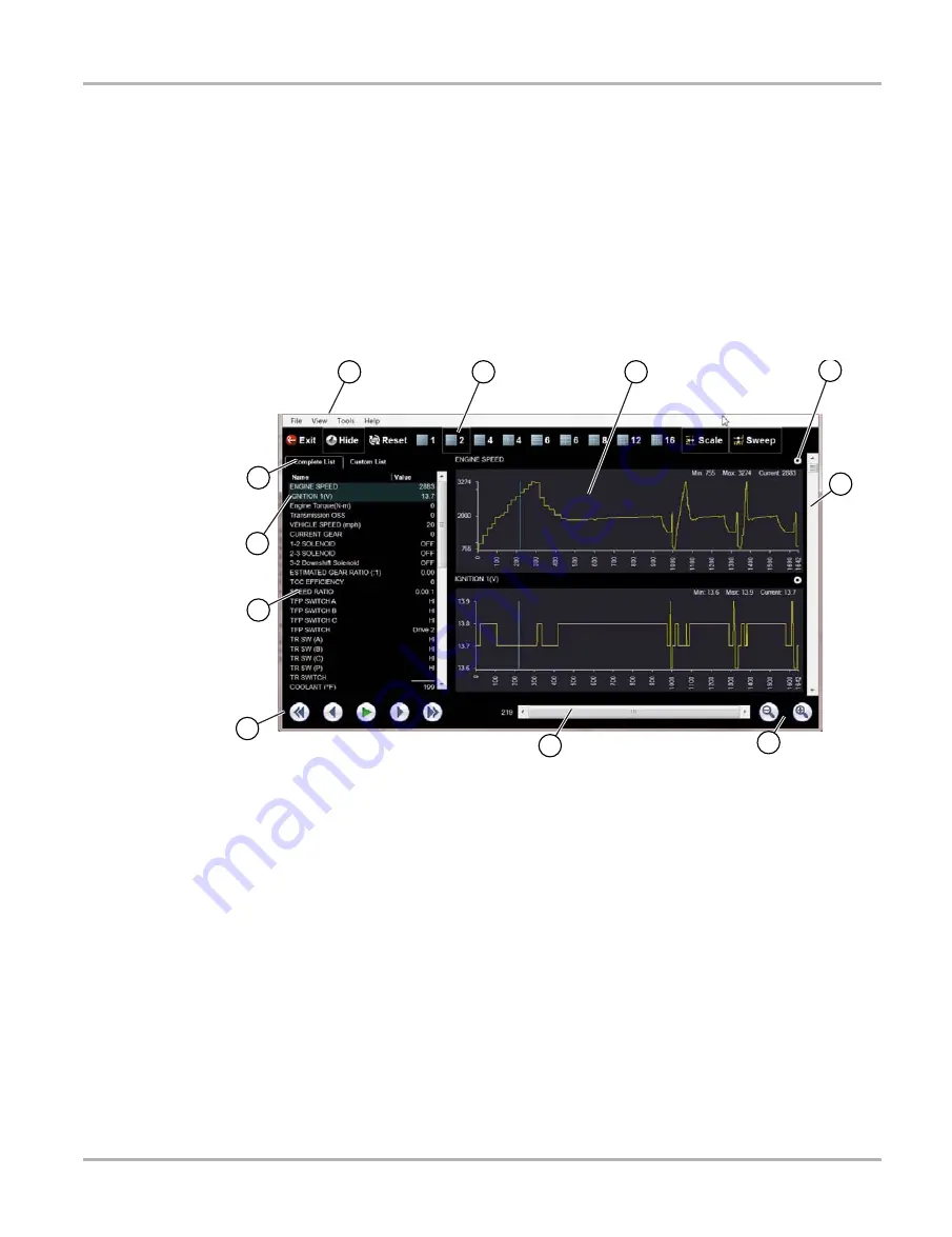
10.3   Scanner DataViewer

SSC allows you to view data files recorded with your diagnostic tool, on your PC. When a Scanner 
data file is selected, it opens and displays in the Scanner DataViewer (

Figure 10-3

). Scanner 

DataViewer allows you play the data file and custom configure the data in a number of ways.

Figure 10-3 

1— Menu bar
2— Display toolbar
3— Graph display
4— Properties icon
5— Vertical Scroll bar

6— Zoom controls
7— Slider bar
8— Navigation toolbar
9— Parameter text list
10—Highlighted PIDs - 

indicates graphs 

currently displayed

11—Parameter configuration tabs

11

9

8

1

2

3

4

5

7

6

10

Summary of Contents for ETHOS+

Page 1: ...User Manual EAZ0078L10A Rev B 1 H 18 GB ...

Page 2: ...p on reserves the right to make changes at any time without notice IMPORTANT Before operating or maintaining this unit please read this manual carefully paying extra attention to the safety warnings and precautions Software License Information Use of Software is governed by the terms and conditions of the End User License Agreement The diagnostic tool should not be initially operated until the End...

Page 3: ... specific training videos are available on our website Follow along and learn the basics of diagnostic tool operation with our free training videos Videos are product specific and are available at http diagnostics snapon co uk Click on the Training and Support tab select Diagnostic Tools then select the applicable diagnostic tool and then select See Quick Tips NOTE i Sample titles are listed below...

Page 4: ... select See Quick Tips https www youtube com user snaponscanner videos Use the search function to find a title or enter Diagnostic Quick Tips in the search field to see a list of all applicable titles NOTE i URL links above and titles listed below are subject to change and may not be available in all markets A sample list of titles are listed below other titles may be available Some videos may not...

Page 5: ...es Ford Battery Monitor System Oil Specs Service Light Resets Ford Coil Current RFI Test Scope PID Trigger Functions Scanner Ford Flash Reprogramming Piezo Injectors Signature Test Ford Misfire Monitor Neutral Profile Correction Scanner Relative Compression Test Scope Ford PATS Key Programming ShopStream Connect Data Manipulation Ford Relative Compression Test ShopStream Connect Software Updates F...

Page 6: ...Buttons 13 Cancel N X Button 13 Shortcut Button 13 Power Button 13 Power Sources 13 Internal Batteries 13 AC Power Supply 14 Vehicle Power 14 Optional Stand and Hand Strap 14 Chapter 3 Getting Started 16 Installing the Batteries 16 Powering Up 17 Home Screen 17 Home Screen Buttons 18 Connecting to a Vehicle 18 The Demonstration Program 19 Powering Down 19 Emergency Shutdown 20 Chapter 4 Navigation...

Page 7: ...gnosis 48 Chapter 7 Previous Vehicles and Data 49 Vehicle History 49 View Saved Data 50 Viewing Codes and Code Scan Results 51 Delete Saved Data 53 Chapter 8 Tools 54 Tools Menu 54 Connect to PC 54 Configure Shortcut Key 55 System Information 55 Settings 56 Configure Units 63 Chapter 9 Maintenance 64 Cleaning and Inspecting 64 Cleaning the Touch Screen 64 Battery Service 64 Battery Safety Guidelin...

Page 8: ...3 Contents End User License Agreement 74 End User License Agreement71 ...

Page 9: ...opriate and acceptable manner that does not endanger your safety the safety of others in the work area the equipment being used or the vehicle being tested It is assumed that the operator has a thorough understanding of vehicle systems before using this product Understanding of these system principles and operating theories is necessary for competent safe and accurate use of this instrument Before...

Page 10: ...ssible consequences of not avoiding the hazard An icon when present gives a graphical description of the potential hazard Example 51 1 Risk of unexpected vehicle movement Block drive wheels before performing a test with engine running A moving vehicle can cause injury Important Safety Instructions For a complete list of safety messages refer to the accompanying safety manual SAVE THESE INSTRUCTION...

Page 11: ...sed in procedures to highlight selectable items such as buttons and menu options Example Press the OK button 1 1 2 Symbols Different types of arrows are used The greater than arrow indicates an abbreviated set of selection instructions Example Select Tools Connect to PC The example statement abbreviates the following procedure 1 Select Tools from the home screen 2 Highlight Connect to PC on the To...

Page 12: ...cles procedures and illustrations are available in electronic documents Blue colored text indicates a selectable hyperlink Example IMPORTANT Read all applicable Safety Information before using this tool 1 1 5 Notes and Important Messages The following messages are used Notes A NOTE provides helpful information such as additional explanations tips and comments Example NOTE i For additional informat...

Page 13: ...entions 1 1 6 Procedures An arrow icon indicates a procedure Example z To change screen views 1 Select the Graph icon The dropdown menu displays 2 Select an option from the menu The screen layout changes to the format selected ...

Page 14: ...r live data parameters on a single screen This chapter describes the construction of the scan tool and addresses the use of the basic hardware controls and features in the following sections Functional Description on page 9 Technical Specifications on page 11 Control Buttons on page 12 Power Sources on page 13 Optional Stand and Hand Strap on page 14 2 1 Functional Description 1 Y a Button Yes Acc...

Page 15: ...ction Functional Description 1 Mini USB Client Port 2 SD secure digital Card Port 3 Data Cable Port Figure 2 2 Top view 4 Battery Compartment Cover Figure 2 3 Back view with optional hand strap and stand 1 2 3 1 ...

Page 16: ...VGA 24 bit color Batteries 6 1 5V AA DC Jack Operating Voltage 8V to 32V DC Dimensions Width 9 15 inches 232 4 mm Height 5 85 inches 148 6 mm Depth 1 85 inches 47 0 mm Weight including batteries 2 0 lbs 907 g Operating Temperature Range ambient At 0 to 90 relative humidity non condensing 32 to 113 F 0 to 45 C Storage Temperature ambient At 0 to 70 relative humidity non condensing 4 to 140 F 20 to ...

Page 17: ...he direction buttons To advance to the next screen in a series To answer Yes when a Yes or No choice is given Button Icon Description Accept Yes Selects a menu or program advances to the next screen or provides a yes answer to a question on the screen Directional Arrows Moves the highlight on the display screen up down left and right as indicated by the arrows Cancel No Exits a menu or program ret...

Page 18: ...ress See Configure Shortcut Key on page 55 for additional information 2 3 5 Power Button The Power button powers up the tool and turns it off 2 4 Power Sources Your Display Device can receive power from any of the following sources Internal Batteries AC Power Supply Vehicle Power 2 4 1 Internal Batteries The scan tool can be powered from the internal batteries New standard batteries or fully charg...

Page 19: ...en connected to an OBD II EOBD DLC there may be a circuit problem on the vehicle Certain vehicles do not provide vehicle power on the DLC For these applications a separate cable adapter and power cable are needed to power the unit Optional data cable adapters are available for testing vehicle from a number of manufacturers Contact your sales representative for availability The optional power cable...

Page 20: ...g Velcro fasteners hold the strap in place and allow for quick adjustments The strap keeps the scan tool snug to the palm of your hand while working The stand extends from the back of the unit to allow hands free viewing The stand clips into the unit for storage and pivots out so that the display is at an angle when in use ...

Page 21: ...stalled before using the tool z To install the batteries 1 Depress the two battery cover lock tabs and lift off the battery cover 1 Battery Cover 2 Lock Tabs Figure 3 1 Battery replacement 2 Observing proper polarity shown on the battery slots install six new AA batteries IMPORTANT Your scan tool can be damaged if the battery polarity is incorrect Refer to the diagram in the battery compartment on...

Page 22: ... the next section and discussed in detail in the Navigation chapter The titlebar which runs across the top of the screen provides information about the current screen or a description of the defined test vehicle The title bar contains no selectable items A graphic indicator at the right edge of the toolbar shows the status of the tool power supply Table 3 1 Power supply icons sheet 1 of 2 Icon Def...

Page 23: ...ollow the screen prompts to identify the vehicle you are testing 4 Fit the 26 pin end of the data cable to the connector on top of the scan tool and tighten the captive screws Indicates power is being supplied by the vehicle Indicates the scan tool is actively communicating with a vehicle Table 3 1 Power supply icons sheet 2 of 2 Icon Definition Table 3 2 Home screen buttons Name Button Descriptio...

Page 24: ...cle to the scan tool while in the Demonstration mode There is also a demonstration program for OBDII EOBD vehicles To access the demonstration select Training Mode from the OBD II EOBD main menu 3 6 Powering Down Use the Power button to turn the scan tool off Holding the Power button down for 4 seconds forces the unit to shut down in the event that it becomes nonresponsive IMPORTANT Vehicle commun...

Page 25: ...20 Getting Started Powering Down 3 6 1 Emergency Shutdown In case of emergency press and hold the Power button to force a shutdown ...

Page 26: ...shows test and tool status 2 Toolbar contains test controls 3 Main body displays menus and test data Figure 4 1 Sample scan tool screen 4 1 1 Title Bar The title bar at the top of the screen provides basic information about current tool operating conditions Title bar options vary depending upon vehicle make and model what test is being performed or what menu is selected Title bar information may i...

Page 27: ...n in Table 4 1 Additional buttons appear on the toolbar when special operations are available These buttons are explained in the Operations chapter Table 4 1 Data toolbar buttons sheet 1 of 2 Button Icon Function Back Returns to the previously viewed screen This button is always at the left hand edge of the toolbar Home Returns to the Home screen This button is always alongside the Back button on ...

Page 28: ... 4 2 Figure 4 2 Sample scroll bar Touch and drag the slider in the center of the scroll bar to quickly move through the data Tap the arrowheads at the ends of the scroll bars to move in the direction of the arrow one line or frame at Lock Unlock Locks or unlocks the highlighted parameter This button displays when viewing a data list Save Saves the current datastream information to tool memory Sele...

Page 29: ...e message automatically clears once the internal operation is complete 4 2 2 Confirmation Messages Confirmation messages inform you when you are about to perform an action that cannot be reversed or when an action that requires your confirmation to continue has been initiated When a response is not required the message displays briefly then disappears 4 2 3 Warning Messages Warning messages inform...

Page 30: ... scan tool information presented is provided by the ECM of the vehicle being tested Therefore certain attributes of the test vehicle must be entered into the scan tool to ensure the data displays correctly This vehicle identification sequence is menu driven simply follow the screen prompts and make a series of choices Each selection advances you to the next screen Exact procedures may vary somewha...

Page 31: ... confirmation displays once all the required data has been entered Figure 5 2 Figure 5 2 Sample confirmation dialog box 4 From the confirmation screen select OK and list of systems displays Figure 5 3 Figure 5 3 Sample available systems list NOTE i Only the systems available for testing on the identified vehicle are included in the list 5 Select a system from the list to continue The identificatio...

Page 32: ... plugs into the adapter which attaches to the data link connector DLC of the test vehicle On screen instructions on the scan tool tell you how to connect the data cable once a test vehicle has been identified The screen message also includes the location of the vehicle diagnostic connector that the cable attaches to for testing the selected system All OBD II vehicles have vehicle battery power B a...

Page 33: ...cle fuse There is a wiring fault on the vehicle There is a circuit fault in the data cable or adapter Incorrect vehicle identification was entered Refer to the Vehicle Communication Software manuals for the manufacturer of the test vehicle for additional troubleshooting information 5 3 Operations The scan tool allows you to establish a data link to the electronic control systems of the vehicle in ...

Page 34: ... Service Codes This selection may appear as Codes Codes Menu Codes Only Codes No Data Service Codes or something similar on the menu Selecting opens a list of data parameter viewing options that include Display Codes Clear Codes Freeze Frame Failure Records DTC Status Display Codes Selecting either opens a list of diagnostic trouble codes DTCs stored in the electronic control module ECM or a subme...

Page 35: ...he control module memory on some vehicles If this function is not available on the test vehicle Clear Codes does not appear on the menu z To clear codes 1 Select Clear Codes from the Codes Menu A confirmation message displays 2 Make sure any conditions shown on the confirmation message are met then select Yes A codes cleared message displays once the operation is complete 3 Select Continue to retu...

Page 36: ...5 3 2 Code Scan One of the benefits of performing a code scan is that you can quickly show your customer diagnostic related issues with a pre scan report and then after repairing the issues you can use the post scan report to show that the repairs were completed Figure 5 7 In addition by using ShopStream Connect the reports can be given to the customer and also saved for your own records for more ...

Page 37: ...e Code Scan results screen Figure 5 8 A progress indicator is shown at the top indicating the active scanning progress Once completed the results are displayed by system category The following Code Scan related control icons are used The following results are displayed progressively as the modules are scanned The total number of systems modules detected Figure 5 8 Icon Function Refresh Restarts th...

Page 38: ... systems analyzed with DTCs totals A categorized system list with DTC totals is displayed in the order they are scanned To view the main menu for a system in the list select the system then select the System icon Figure 5 9 Figure 5 9 System icon opens Main Menu Vehicle Information Vehicle Information ...

Page 39: ...ic tool See View Saved Data on page 50 Using ShopStream Connect See ShopStream Connect on page 67 Printing the Code Scan Report The vehicle system report can also be customized and printed using ShopStream Connect See Printing the Code Scan Report on page 71 Clear All Codes Read by Code Scan Selecting Clear All Codes Read by Code Scan erases all DTCs from all vehicle system modules that were read ...

Page 40: ...isplays a description of the parameter and the right hand column shows the parameter value or state Parameters are listed in the order in which they are transmitted by the ECM so there will be variation between makes and models Pausing Data Collection You can pause the collection of data being transmitted from the vehicle ECM When data is paused a number of previous frames of vehicle data before p...

Page 41: ...vious Frame or Next Frame Each button touch moves one frame in the selected direction z To resume collecting data Touch the Record button The display changes to live data and the Pause icon is shown on the toolbar The display also returns to text mode if that was the mode being used before data collection was paused NOTE i The Shortcut button can be set to perform the Pause Play function See Confi...

Page 42: ...ith a lock icon and cannot be selected IMPORTANT Limiting the number of parameters that display results in a faster data refresh rate and reduces the amount of memory used for saved files z To create a custom data list 1 Tap the Custom Data List button on the toolbar The data selection screen displays and two new buttons appear on the toolbar The toolbar buttons provide options for selecting and d...

Page 43: ...utton to return to the data display 3 Select OK to display the updated data list Changing Screen Views Select the View button to open a dropdown menu of options PID List 1 Graph 2 Graph 4 Graph The PID parameter identification List view is a 2 column display with the name of the parameters in the left column and their current values in the right column Figure 5 10 Graph views divide the screen hor...

Page 44: ...ap the Lock Unlock button on the toolbar The display is now in lock mode and it remains in this mode until another button is selected 2 Tap anywhere within a parameter frame to lock it The parameter is highlighted a lock icon displays alongside it to indicate that it is locked and the parameter displays in the upper frame on the screen Figure 5 13 3 Select additional parameters to lock if desired ...

Page 45: ... tool to automatically capture data when a parameter value crosses a threshold value When triggering is armed a trigger event pauses data collection and records a data movie similar to an OBD II EOBD freeze frame event Selecting the PID Trigger opens a menu that includes Set Trigger establishes upper and lower signal values to initiate an event capture for the highlighted parameter Arm Trigger act...

Page 46: ...ws and press a The display returns to live data and the trigger points appear as horizontal lines across the parameter graphs Repeat to establish trigger points for other parameters if desired Once armed any data points that register outside the set conditions pause data collection and save a recording NOTE i Only three parameters can have trigger levels set at one time but only one of the conditi...

Page 47: ...c control module ECM may occur if communication is disrupted Make sure the data cable and the USB cable are properly connected at all times during testing Exit all tests before disconnecting the test cable or powering down the tool z To exit scan tool tests 1 From an active screen select Exit from the toolbar to return to the Systems Menu 2 From the Systems Menu select Back A stopping communicatio...

Page 48: ...u with these options Start Communication begins the test session Select Communication Protocol allows you to select which protocol to use Connector Information provides data link connector DLC location details for most models End of Diagnosis ends communication between the scan tool and the vehicle The OBD Training Mode is a demonstration program that allows you to access OBD II EOBD scan tool fun...

Page 49: ...hicle according to the screen instructions 4 Select Continue A communications message that shows how many ECMs were detected Which ECM is communicating and which communication protocol is being used displays Figure 6 2 Figure 6 2 Sample communication message 5 Select Continue A menu of available tests displays Figure 6 3 ...

Page 50: ... Tracking 0A Emission Related DTC with Permanent Status Readiness Monitors Use this menu item to check the readiness of the monitoring system If a monitor system is not supported it is not displayed Scroll if needed to view the entire list of monitors Selecting Readiness Monitors opens a submenu of choices Monitors Complete Since DTC Cleared displays the results of all monitor tests that have run ...

Page 51: ... cases the highest priority DTC is the one for which the freeze frame records are retained in memory Freeze frame data includes a snapshot of critical parameter values at the time the DTC set 03 Display Trouble Codes This is used to display any stored emission related DTCs reported by the various ECMs 04 Clear Emissions Related Data This item is used to clear all emission related diagnostic data s...

Page 52: ...ith Permanent Status This option displays a record of any permanent codes A permanent status DTC is one that was severe enough to illuminate the MIL at some point but the MIL may not be on at the present time Whether the MIL was switched off by clearing codes or because the setting conditions did not repeat after a specified number of drive cycles a record of the DTC is retained by the ECM Permane...

Page 53: ... vehicle diagnostic connector locations that includes most makes and models The menu driven interface leads you quickly to the difficult to find test connector z To locate a vehicle diagnostic connector 1 Select Connector Information from the System menu 2 Select a manufacturer from the list presented 3 Select a model from the list presented 4 Select Continue and connector location information dis...

Page 54: ...s have been made The oldest vehicle record is deleted when a new vehicle is identified once there are twenty identifies on file z To select from a vehicle in history 1 Tap Previous Vehicles and Data on the Home screen 2 Select Vehicle History from the menu A list of up to 25 previously tested vehicles displays file names include the vehicle ID date and time Use the scroll bar to view the entire li...

Page 55: ...t files are at the top of the list The vehicle ID characteristics are included in the listings as well Figure 7 2 Figure 7 2 Sample saved vehicle data list z To review a movie 1 Tap Previous Vehicles and Data on the Home screen 2 Select View Saved Data from the menu 3 Select a movie from the list of saved files The movie opens and plays in real time The Play button changes to the Pause button at t...

Page 56: ...tem code results are saved they are saved in XML file format Figure 7 3 Figure 7 3 Typical Code Results XML file The saved XML file s can be viewed using these methods On the diagnostic tool See Viewing Code Results on the Diagnostic Tool on page 52 In report format using ShopStream Connect see Printing the Code Scan Report on page 71 ...

Page 57: ...agnostic Tool Selecting a system code or a code scan results file from your saved file list Figure 7 4 opens the file onscreen When opened the XML file displays basic vehicle information and a list of DTCs with a brief description of each Figure 7 4 Typical Code Scan Results XML file viewed onscreen ...

Page 58: ...re available on the toolbar Use the Select Deselect button to delete individual files use the Select All Deselect All buttons to clear the entire memory buffer at once 3 Select a file to delete from the list and a confirmation message displays 4 Select an option from the confirmation message OK removes the selected file and returns to display the saved files list which no longer includes the delet...

Page 59: ...to your personal computer using a USB cable The optional ShopStream Connect PC software allows you to view print and save data files on your PC In addition you can download software updates from the PC to the Diagnostic Tool These features provide an ideal way to manage saved data files The ShopStream Connect application is available free online see ShopStream Connect on page 67 for additional inf...

Page 60: ...ble parameter Show Menu Shortcuts opens the Configure Shortcuts menu when the Shortcut button is pressed so you can quickly select from any of the available functions Toggle Record Pause programs the Shortcut key to work as the Pause and Play buttons while viewing data the first press pauses data collection and the second press resumes live data capture z To assign a function to the Shortcut key 1...

Page 61: ...sed to calibrate the touch screen display Time Zone is used to set the internal clock to the local time standard Clock Settings is used to set the real time clock that displays on the title bar Daylight Savings Time is used to configure the internal clock for Daylight Savings Time Time Format is used to configure whether time is displayed on a 12 or 24 hour clock Date Format is used to configure t...

Page 62: ...can tool to increase the screen illumination 2 Tap the Minus button on the touch screen or use the down d arrow to decrease screen the screen illumination Each tap or button press incrementally changes the display screen back lighting 3 To exit select Back or Home from the toolbar or press the N X cancel button Touch Calibration Calibrating the touch screen maintains the accuracy of the touch sens...

Page 63: ...ation procedure is complete Time Zone This option opens a menu of time zone settings Scroll to highlight then select the local time zone The display returns to the Settings menu once a time zone is selected Clock Settings The system clock setting screen opens when this option is selected from the Setup menu Figure 8 9 TOUCH SCREEN CALIBRATION WARNING Do not power the tool off until the Touch Calib...

Page 64: ...t select either Back or Home from the toolbar or press the X cancel button to exit NOTE i The Time Format on page 59 option is used to switch between a 12 hour and 24 hour clock Daylight Savings Time This option configures the internal clock for Daylight Savings Time Select Yes or No to return to the Settings menu Time Format This option allows you to select whether time displays on a 12 or 24 hou...

Page 65: ... easier to see in poor lighting conditions or bright sunlight Figure 8 6 Sample high contrast toolbar Selecting opens a menu with two choices Make a selection and a please wait message momentarily displays followed by the Home screen The new toolbar setting is now active Color Theme This option allows you to select between the standard white default and a black night background for the screen The ...

Page 66: ...age momentarily displays followed by the Home screen The new toolbar setting is now active Font Type This option allows you to select between standard and bold faced type for the display screen The bold type option is designed to make screen writing more legible under poor lighting or bright sunlight conditions Figure 8 8 Sample bold type on a black background ...

Page 67: ...teries Figure 8 9 The rechargable setting is designed to maximize battery life An on screen message displays in the rechargeable mode when the batteries are in need of a charge Figure 8 9 Sample battery type screen Backlight Time This option allows you to configure how long the screen backlight remains on when the tool is inactive The following choices are available Always On 15 Seconds 30 Seconds...

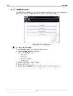
Page 68: ...8 10 Figure 8 10 Sample configure units menu z To change the units setup 1 Select Tools from the Home screen to open the menu 2 Select Configure Units from the menu A menu of options displays Temperature Air Pressure Pressure all others Vehicle Speed 3 Select an item to open a list of choices 4 Select a setting from the list 5 Press N X or tap the Back button on the toolbar to return to the option...

Page 69: ...can be cleaned with a soft cloth and a mild window cleaner IMPORTANT Do not use any abrasive cleansers or automotive chemicals on the touch screen 9 2 Battery Service Follow all safety guidelines when handling the batteries 51 1 Risk of electric shock Prior to recycling the batteries protect exposed terminals with insulating tape to prevent shorting Disconnect all test leads and turn diagnostic to...

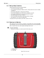
Page 70: ...pack out of reach of children Do not use a battery that appears to have suffered abuse or damage Store batteries in a cool dry well ventilated area To prolong the life of your batteries power off the unit when not in use 9 2 2 Replacing the Batteries When replacing the scan tool batteries use Alkaline or rechargeable nickel metal hydride NiMH type AA batteries only Do not use standard lead zinc ba...

Page 71: ...set the battery type on the Tools Setup menu This helps prolong the life of the batteries and notifies you when it is time to recharge them 9 2 3 Disposing of the Batteries Always dispose of batteries according to local regulations which vary for different countries and regions For additional information contact United Kingdom Electrical Waste Recycling Company at http www electricalwaste com Prod...

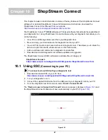
Page 72: ...to share the data in a report format with vehicle owners or other technicians Add or edit notes and comments to diagnostic tool data files Download and install diagnostic tool software updates and upgrades The ShopStream Connect SSC software is available free of charge at ShopStream Connect https www snapon com diagnostics UK Diagnostics ShopStreamConnect htm 10 1 Using SSC Connecting to your PC z...

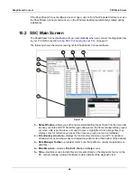
Page 73: ...m the menu bar to save your notes NOTE Not all file types allow notes the Notes window will be grayed out when a file type that does not support notes is highlighted Some image files may display notes for reference purposes the notes are grayed out and not editable 2 File directory structure displays the file directory structure of your PC in standard Windows format and shows any connected diagnos...

Page 74: ...r DataViewer SSC allows you to view data files recorded with your diagnostic tool on your PC When a Scanner data file is selected it opens and displays in the Scanner DataViewer Figure 10 3 Scanner DataViewer allows you play the data file and custom configure the data in a number of ways Figure 10 3 1 Menu bar 2 Display toolbar 3 Graph display 4 Properties icon 5 Vertical Scroll bar 6 Zoom control...

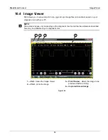
Page 75: ...iagnostic tool with your PC NOTE i File extension types vary depending on the diagnostic tool Not all the file extensions described here may be available on your diagnostic tool Figure 10 4 1 Exit closes the Image Viewer 2 Print prints the image 3 Print Preview allows the image to be previewed before printing 4 Captured Screen Image 4 3 1 2 ...

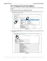
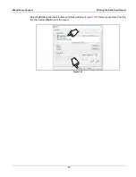
Page 76: ...opened using ShopStream Connect To print the Code Scan Report using ShopStream Connect 1 Double click the code scan XML file from the file list to open the report Figure 10 5 in the Code Scan Viewer Figure 10 6 Figure 10 5 2 Select Print or Print Preview from the Code Scan Viewer menu to print or preview the report Figure 10 6 Figure 10 6 Diagnostic Tool ...

Page 77: ... Connect Printing the Code Scan Report Selecting Print opens the Windows print dialog window Figure 10 7 Select your printer from the list then select Print to print the report Figure 10 7 My printer 1 My printer 2 ...

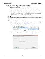
Page 78: ...stalled on your PC and have connection to the Internet z Example Updating diagnostic tool software 1 Select Tools Update Software diagnostic tool type e g ETHOS Edge MODIS Edge SOLUS Edge etc from the Menu bar Figure 10 8 The software checks the Snap on web server for available updates Figure 10 8 2 If service release updates are available select Next to continue then select Download and follow th...

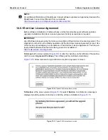
Page 79: ...should not be initially operated until the End User License Agreement is read Use of the device acknowledges your acceptance of the End User License Agreement The Snap on Incorporated Software End User License Agreement is available at https eula snapon com diagnostics To Accept at the screen prompt Figure 10 10 click the checkbox on the left side of the window and then select Agree and Continue T...

Reviews: