background image

12

Snap-on Tools Corporation  Kenosha, WI 53141-1410

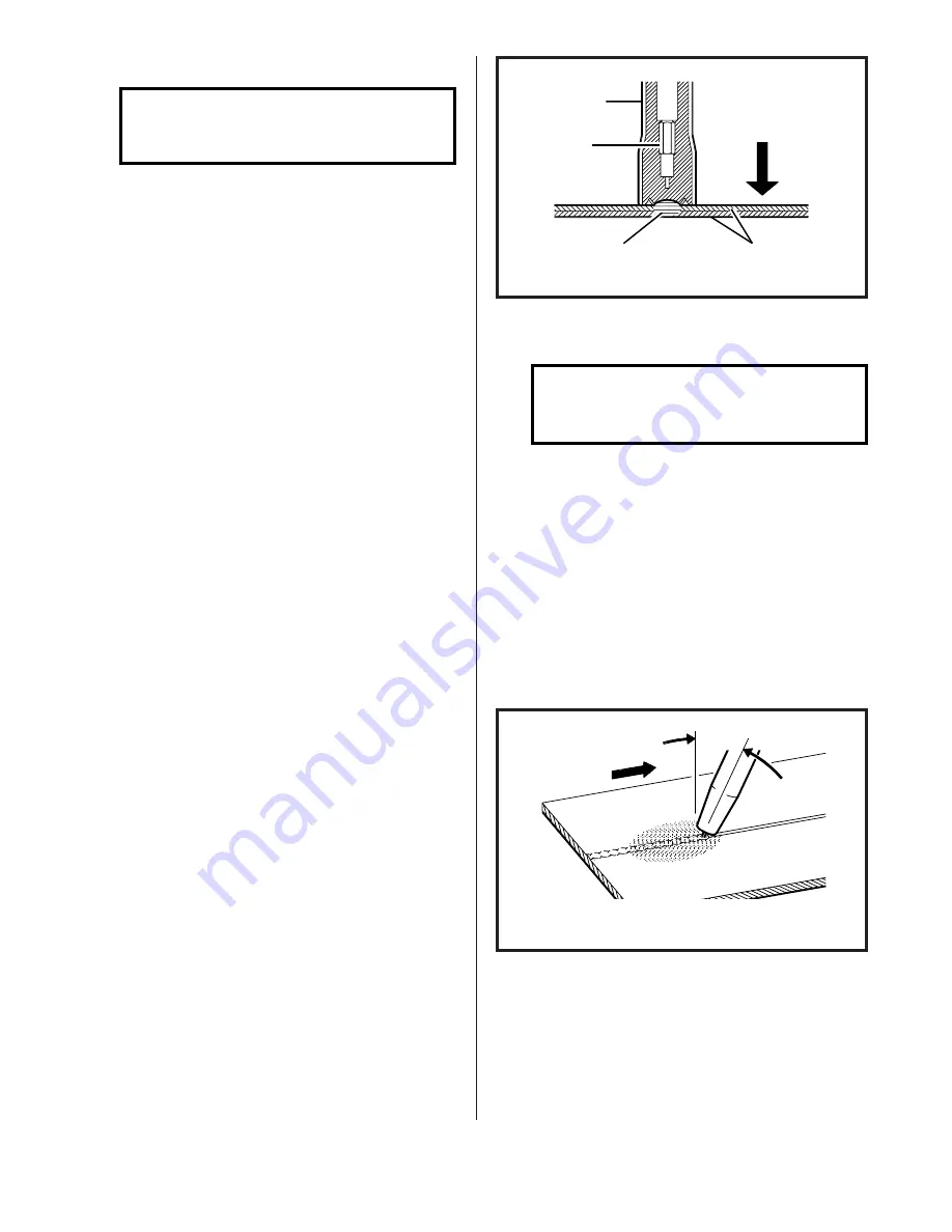
MIG SPOT WELDING ON STEEL

NOTE

MIG Spot Welding is NOT
recommended for aluminum.

1. Trim the electrode wire so the

stickout from the contact tip
will be flush with the nozzle
face, and fit the spot nozzle in
place.

2. Set the VOLTAGE on the welder

around 20 volts, the WIRE FEED
control "8", the MODE Switch to
"SPOT", and the TIME control to
"3", then adjust the controls to
obtain a perfect weld.

3. Locate the torch on the area to

be welded and press the nozzle
firmly against the work to hold
the metals in place.

4. Guard the eyes against stray arc

flash. A weldor’s helmet is not
necessary when spot welding,
however, care must be taken to
avoid looking at the arc.

5. Activate the torch trigger to

start the weld sequence. When
the timer switches off the weld
current, release the trigger but
maintain firm contact between
the torch and work. Wait one
second for the weld puddle to
solidify, then move to the next
spot position. If the wire
"freezes" in the puddle, a quick
squeeze of the torch trigger
will melt it off.

6. To ascertain a good spot weld,

look at the back side of the
welded material. A small melt-
through  of approximately 1/16
inch diameter is ideal.

SPOTWELD

WORK

PRESS NOZZLE

FIRMLY

AGAINST WORK

SPOTWELD

NOZZLE

CONTACT

TIP

FIG. 16.  MIG SPOT WELDING

STITCH WELDING ON STEEL

NOTE

Stitch Welding is used for
very light material.

1. Set MODE Switch to "STITCH".

2. Adjust the TIME control to set

the time the welder is "on" and
feeding wire. The lower the
setting, the shorter the "on"
time and the faster the unit
cycles on and off.

3. Weld using "Continuous Welding"

torch position and direction of
travel.

FIG. 17.  STITCH WELDING

DIRECTION
OF TRAVEL

30 DEGREES

WORK

SHIELDING GAS

Summary of Contents for MM140SL

Page 1: ...LUSIVELY FROM SNAP ON TOOLS THE SNAP ON MUSCLE MIG SYSTEM MODEL MM140SL IS DESIGNED AND ENGINEERED BY THE PROS FOR THE PROS UNDER NORMAL CARE THIS SYSTEM WILL PROVIDE YOU WITH YEARS OF UN SURPASSED SERVICE AND MOST IMPORTANTLY PERFORMANCE FOR TECH SERVICE CALL TOLL FREE 1 800 232 9353 INSTALLATION OPERATION MAINTENANCE FORM WC5376 Rev 11 98 1 00 8 00 4 01 ...

Page 2: ...AGES SO THE ABOVE LIMITA TIONS OR EXCLUSIONS MAY NOT APPLY TO YOU THIS WARRANTY GIVES YOU SPECIFIC LEGAL RIGHTS AND YOU MAY HAVE OTHER RIGHTS WHICH MAY VARY FROM STATE TO STATE ARC WELDING CAN BE INJURIOUS TO OPERA TOR AND PERSONS IN THE WORK AREA CONSULT INSTRUCTION MANUAL BEFORE OPERATING ELECTRIC SHOCK can kill Do not touch electrodes or other electrically live parts Insulate yourself from work...

Page 3: ...igher Never change fuses or circuit breakers to a higher value than the wires and outlet are designed for Breaker size Wire size 15 Amp 14 Gauge 20 Amp 12 Gauge 30 Amp 10 Gauge Do not rely on the circuit breaker built into the MM140SL to protect your wiring This circuit breaker protects the MM140SL internal wiring only Do not use undersized extension cords Follow the cord manufacturer s recommenda...

Page 4: ...ional MHG5 B spool gun optional liners must be purchased to cover given wire sizes Heavier sections can be easily welded using slightly different techniques The number of controls on the unit have been reduced to assist inexpe rienced operators to learn MIG welding This facilitates rapid set up for welding various thick nesses of material requiring vari ous heat inputs The VOLTAGE control adjusts ...

Page 5: ...rrent see below OUTPUT POWER 100 Duty Cycle 15 Amps Input Current 100 Amps 20 Amps Input Current 120 Amps 30 Amps Input Current 140 Amps DUTY CYCLE TIME PERIOD 10 minutes OPEN CIRCUIT VOLTAGE 18 33 volts DC ARC VOLTAGE 14 26 volts DC WELD CURRENT RANGE 30 140 amps REMOTE FEED UNIT Input Voltage 28 VAC Wire Feed Speed Range 50 800 IPM DUTY CYCLE SPOT WELDING 30 X 2 second spots per 10 minute period...

Page 6: ...r welding helmet with proper colored lens shade 9 to 11 depending on operator s pref erence 2 Proper shielding gas and cylin der 3 Leather welding gloves 4 115 volt single phase AC power 5 Other personal protective equipment which may vary to match the welding being per formed INSTALLATION POSITIONING THE UNIT Locate the unit adjacent to the welding area and position it so there is adequate cleara...

Page 7: ...ter from the valve CAUTION Take care to point the valve outlet away from yourself or other people as escaping high pressure gas may be dangerous 3 Attach the gas regulator flow meter supplied with this unit to the cylinder valve using a suitable wrench NOTE If this unit is to be used with 100 CO2 shielding gas an optional gas regu lator coupler is required 4 Fit the gas hose from the welding machi...

Page 8: ...ire cutters The wire must be straight when it enters the inlet guide TORCH CONNECTION 1 Open the access door of the Feed unit to its fullest extent 2 Back out the thumb screw located on the drive assembly mounting bracket inside the machine In sert the MIG torch into the torch panel mount on the front panel and TIGHTEN THE THUMB SCREW DRIVE ASSEMBLY MOUNTING BRACKET DRIVE ROLL TORCH PANEL MOUNT TH...

Page 9: ...the torch approximately six inches CAUTION Keep hands and face away from the front of the torch and do not allow the wire to contact ground The wire is electrically HOT when the torch trigger is actu ated 8 9 10 11 Install the contact tip over the protruding wire and tighten it firmly using a proper size wrench Make sure the tip is the correct size for the wire being used Install the nozzle on the...

Page 10: ...olls start to slip If the wire will not feed with very little pressure applied the pres sure roll adjusting nut should be tightened OPERATING SEQUENCE Make sure that the pieces of metal to be welded are free of grease dirt paint and scale Use a wire brush to remove paint and scale Paint must be com pletely removed to bare metal Grease and oil could burn and cause a fire or safety hazard Failure to...

Page 11: ...ding machine CONT posi tion is for normal continuous welding operation SPOT posi tion puts the spot timer in the circuit for automatic MIG Con sumable Spot Welding STITCH position is used for stitch welding on very light materials K WIRE SPEED Potentiometer controls speed of wire drive motor to give wire speed of 50 to 800 inches per minute A GAS CURRENT TERMINAL B CONTROL RECEP TACLE INPUT C MIG ...

Page 12: ...it or on page 25 for optimum results using the sample material thickness and wire size being used as a starting point weld until experi ence is gained using the unit CONTINUOUS WELDING ON STEEL 1 Trim the electrode wire to leave approximately 1 4 inch stickout beyond the end of the contact tip and install the welding nozzle The contact tip should be flush or stick out up to 1 16 inch beyond the en...

Page 13: ...torch trigger The wire will feed and an arc will be established As the weld is deposited move the torch slowly along the weld seam at a constant speed while maintaining a con stant arc length and a constant tip to work distance CONTINUOUS WELDING ONALUMINUM Optional Nylon liner and 100 Argon shielding gas are required 1 Trim the electrode wire leaving approximately 1 inch stickout beyond the end o...

Page 14: ...equence When the timer switches off the weld current release the trigger but maintain firm contact between the torch and work Wait one second for the weld puddle to solidify then move to the next spot position If the wire freezes in the puddle a quick squeeze of the torch trigger will melt it off 6 To ascertain a good spot weld look at the back side of the welded material A small melt through of a...

Page 15: ...and the nozzle can cause a short circuit and consequently failure of the torch or welding machine The frequent use of anti spatter spray will help prevent the adher ence of spatter to the torch compo nents NOTE DO NOT use any anti spatter spray when welding aluminum or stainless steel Restricted gas flow holding the torch too far from the work piece and the use of CO2 gas rather than 75 Argon 25 C...

Page 16: ...hould stand by with a fire extinguisher or other fire protective device NEVER weld on a closed vessel or one that has contained combustibles IF IN DOUBT DON T DO IT BE SAFE DON T BE SORRY 2 Remove dirt and metal deposits from the grooves in the feed roll If the grooves are badly worn the feed roll should be replaced If the pressure roll does not turn freely it should be replaced 3 Check all gas fi...

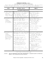
Page 17: ...able Check torch cable activated for continuity no response Loose or broken connection Check or repair on wiring harness PLG2 connections Wire feed motor unplugged Plug in motor RC5 Faulty control transformer Check for 28VAC output T2 Loose spot timer circuit Install properly board PC2 Defective spot timer Replace board circuit board CR2 PC2 Main power on Pressure roll arm unlatched Latch arm add ...

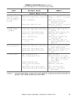
Page 18: ...lding gas Replace tank torch tank empty trigger Loose or broken Tighten or repair activated connections connections no gas flow Faulty Gas solenoid Repair or replace but contactor valve GS valve operates Clogged gas flow path Locate clean clog wire feeds Loose spot timer circuit Install properly board PC2 Defective spot timer Replace board circuit board CR2 PC2 FAULTY WELDS Jerky or Worn kinked or...

Page 19: ...ne settings Increase heat wire puddle speed Incorrect shielding gas Replace with proper gas Excessive wire stick out Hold torch closer to work Poor connections Check and tighten all connections Faulty diode Test diodes replace D1 D2 faulty diode s See page 18 Heavy spatter Incorrect machine settings Increase heat decrease wire feed speed Incorrect shielding gas Replace with proper gas Excessive wi...

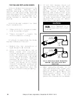
Page 20: ...tions If there is no continuity in either direction the diode is in open circuit condition and must be replaced If there is continuity in both direc tions the diode is in short circuit condition and must be replaced If there is continu ity in one direction only the diode is functioning properly 3 If all the diodes check out satisfactorily with the Volt Ohm Meter a load check must be made This is e...

Page 21: ...Remove the top cover assembly from the base unit 2 Locate the printed circuit boards 3 Referring to Figure 19 locate the trim resistor this is lo cated in the upper right hand corner of the wire feed PC board 4 Turn the wire speed dial on the front of the machine to 0 5 Remove any tension on the drive roll 6 Activate the torch trigger 7 Rotate the trim resistor back and forth until the bottom driv...

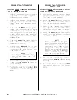
Page 22: ...rm WC5229 7 To change back to standard MIG operation reverse the proce dure CONNECTING THE FLEXTIG CHANGING FROM STANDARD MIG OPERA TION TO FLEXTIG OPERATION CHANGING FROM STANDARD MIG OPERA TION TO SPOOL GUN OPERATION 1 Unplug the feeder control cable plug from the control receptacle OUTPUT of the welder 2 Plug the MHG5 B spool gun con trol cable plug into the welder control receptacle OUTPUT 3 R...

Page 23: ...onnector end of the torch as sembly see FIG 21 Grip the liner and gas seal firmly then pull The liner should easily slide from torch assembly 1 2 3 4 5 4 5 Install the new liner into the MIG torch assembly until gas seal seats flush with the con nector plug Tighten set screw Do not over tighten refer to FIG 21 6 7 Following the diagram in FIG 22 measure out 1 1 4 from the neck assembly and cut off...

Page 24: ...or Spray Arc Welding ORIFICE 1 2 Longer 1 Longer WIRE SIZE PART NUMBER CUP PART NUMBER PART NUMBER PART NUMBER CUP 1 2 I D M3 C50L M3 C50XL INS BUSHING M3H B 020 025 inch M3 ST25 Flared CONTACT TIP NOZZLE NUT M3H NN 030 inch M3 ST30 Cup 020 025 inch M5 T25 M5 LT25 SPOT NOZZLE 035 inch M3 ST35 5 8 I D 030 inch M5 T30 M5 LT30 FlatSpot M3H NS1 040 047 inch M3 ST45 M3 C62 035 inch M5 T35 M5 LT35 Insid...

Page 25: ...G SCREW M3 212 TRIGGER ADJUSTING SCREW ONLY M3 213 TRIGGER PIN M3 214 TRIGGER SPRING QUICK CONNECTOR GROUP M3 120 FERRULE M3 301A CONNECTOR HOUSING M3 305A CONNECTOR STEM M3 306 CONNECTOR PLUG WITH SETSCREW O RINGS M3 307 SETSCREW ONLY M3 308 O RING ONLY 2 REQUIRED M3 309 TERMINAL CONNECTOR CONTACT 2 REQUIRED M3 310A BOOT CABLE SUPPORT M1 401 HANDLE M3 402 HANDLE SCREW 2 REQUIRED M3 405 TERMINAL T...

Page 26: ...Locking Switch onTorch MHG5 B ONE POUND SPOOL GUN FOR ALUMINUM MIG WELDING WITH SNAP ON TOOLS MUSCLE MIG SYSTEMS MM140SL MM250SL The MHG5 B Motorized Hand Gun System is a compact light in weight easy to operate MIG welding system designed for aluminum welding It will feed 023 Thru 3 64 diameter wire from 4 inch spools The standard equipment cable is 25 feet in length 35 foot and 50 foot cables are...

Page 27: ...O2 Min 1 8 7 6 1 2 3 16 8 7 1 4 8 8 20 Ga 036 1 2 1 2 18 Ga 048 2 3 16 Ga 060 3 4 14 Ga 075 4 4 12 Ga 105 5 5 035 1 8 6 5 3 16 7 5 1 2 1 4 8 6 5 16 8 6 3 8 8 6 PROPER DRIVE ROLL ORIENTATION USE LARGE USE SMALL GROOVE FOR GROOVE FOR 045 DIA WIRE 023 035 DIA WIRE Position adjusting collar to align drive roll groove with centerline of wire guide tube Then secure drive roll with the washer and the nut...

Page 28: ...Snap on Tools Corporation Kenosha WI 53141 1410 ...

Reviews: