Snap-on Tools Corporation Kenosha, WI 53141-1410
5
INSTALLING THE FEEDER CONTROL CABLE
ASSEMBLY (Cont.)
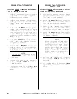
4. Plug the power plug into the
positive (+) terminal(located
on the front of the welding
machine).
5. Connect the control plug (male
pins) onto the control recep-
tacle (OUTPUT)and tighten (lo-
cated on the front of the welding
machine).
FIG. 5. CABLE CONNECTION TO
WELDING MACHINE
WELDING
MACHINE
TO CONTROL
RECEPTACLE
(OUTPUT)
TO (+)
TERMINAL
(STANDARD)
SHIELDING GAS CONNECTIONS
1. Place a cylinder of the appro-
priate shielding gas in the rack
at the rear of the machine and
secure it with the chain pro-
vided.
2. Rapidly open and close the cyl-
inder valve. This will purge
dust and foreign matter from the
valve.
CAUTION
Take care to point the
valve outlet away from
yourself or other people,
as escaping high pressure
gas may be dangerous.
3. Attach the gas regulator - flow-
meter supplied with this unit,
to the cylinder valve using a
suitable wrench.
NOTE
If this unit is to be used
with 100% CO2 shielding
gas, an optional gas regu-
lator coupler is required.
4. Fit the gas hose from the welding
machine to the regulator outlet
fitting and tighten it with a
wrench. Open the cylinder valve.
When welding steel, the gas flow
rate is 30 CFH. When welding
aluminum, the gas flow rate is 40
CFH.
NOTE
The MM140SL must be turned
"ON" and the MIG torch
trigger depressed, before
the gas flow rate can be
adjusted.
FIG. 6. GAS FLOW ADJUSTMENT
GAUGE -
INDICATES
TANK
PRESSURE
OUTLET
FITTING
TO
WELDING
MACHINE
GAS FLOW
ADJUSTING
KNOB
INLET
FITTING
TO
TANK
FLOW TUBE
INDICATES
FLOW RATE
IN C.F.H.


