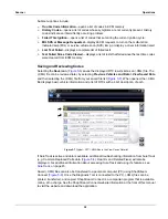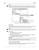
20
Navigation
Guided Component Tests and Scope Multimeter Navigation
4.3 Guided Component Tests and
Scope Multimeter Navigation
This section describes general navigation for Guided Component Test and Scope Multimeter
screens. Although there are some differences, the interface operates similarly for both modules.
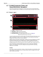
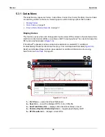
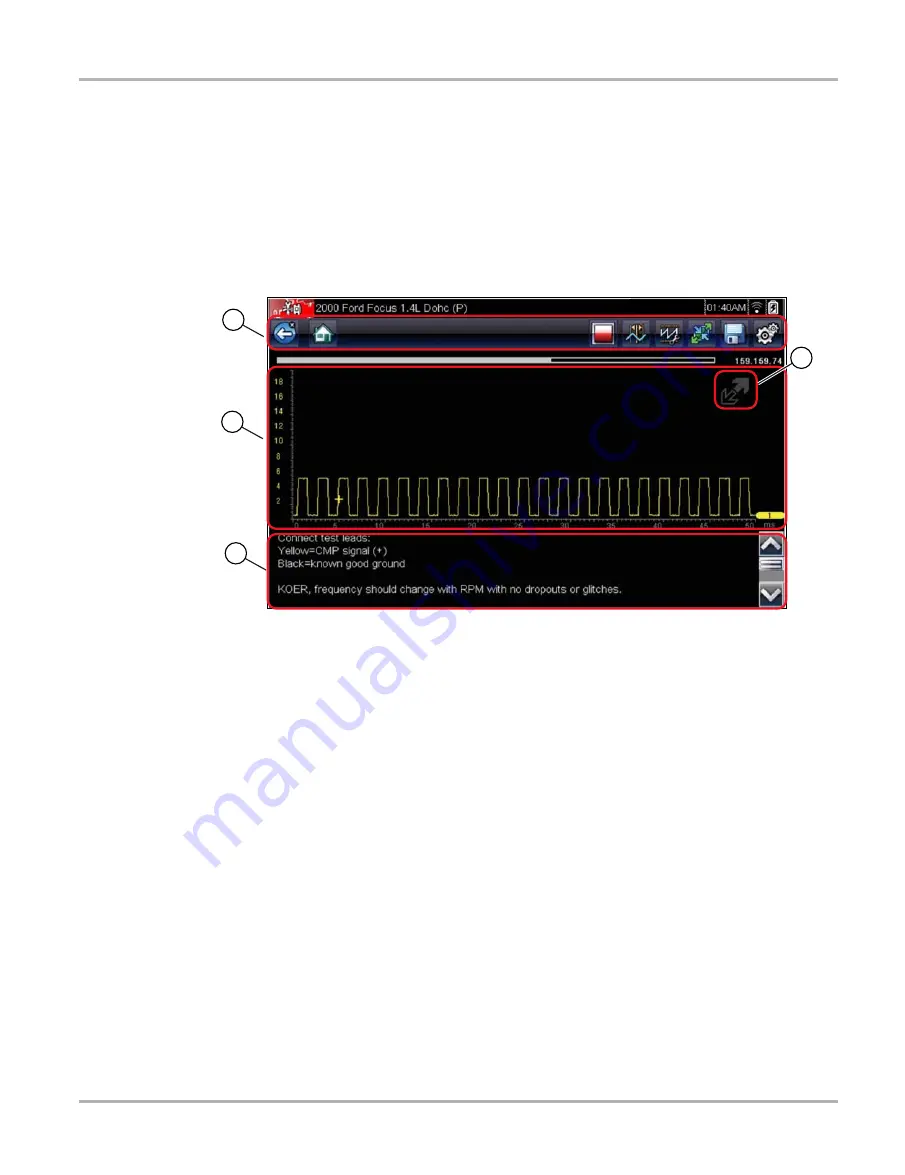
4.3.1 Screen Layout
1— Toolbar
—contains test controls
2— Main Body
—displays menus and test data
3— Information Panel
—shows test and tool status
4— Expand/Collapse icon
—operates like the toolbar button, see
Figure 4-3
Sample Guided Component Test screen
A typical Scope Multimeter screen would be similar to the Guided Component Test screen shown
above, and navigation is similar as well. The differences are in the information that is being
displayed on the screen, and how the data is gathered.
Guided Component Test data is vehicle specific. Therefore, the meter that displays is configured
to perform the selected test on the identified vehicle. In addition to displaying test results;
procedures, tips, and specifications for the selected test are available at the touch of a button.
Scope Multimeter tests are more general and not tied to a specific vehicle. Therefore, there is no
need to go through the vehicle identification sequence when using the Scope Multimeter.
However, more adjustments to the meter settings are usually needed and the supporting
information is not available.
Toolbar
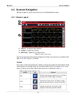
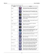
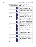
The toolbar, located under the title bar, contains a number of selectable tool control buttons. What
buttons appear on the toolbar varies, as only buttons that are active or available for the current
screen and test mode display.


