22
Navigation
Guided Component Tests and Scope Multimeter Navigation
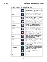
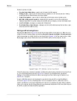
Additional buttons appear on the toolbar when special operations are available. These buttons are
explained in the operations chapters where applicable.
Main Body
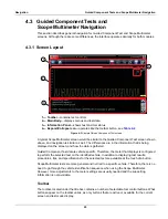
The main body of a Guided Component Test screen displays one of three things:
•
A selectable menu
•
Component information
•
A test meter
The main body of a Scope Multimeter screen displays:
•
A selectable menu
•
A test meter
Select from a menu using the touch screen or the control buttons.
Component Information screens contain information to assist you with testing.
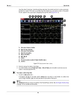
Test meters can display two circuit traces, or waveforms, simultaneously. Adjustments to the
display are made through the toolbar. Each trace is displayed as voltage over time on a standard
oscilloscope screen. Voltage level is recorded on the vertical, or “y”, axis and time is presented on
the horizontal, or “x”, axis of the screen. Values are shown for each graduation on the scales.
Touch screen functionality within the main body of the screen is limited, most adjustments are
performed from the Toolbar and the Profile window. However, you can adjust the following in the
main body:
•
Trigger position; touch and drag the trigger indicator (+) to reposition it.
•
The expand/collapse icon in the upper-right corner of the main body performs the same
function as the Expand/Collapse button on the Toolbar.
•
The baseline position (0 value) of the trace can be repositioned on the horizontal scale by
touching and dragging the solid bar at the right-end of the channel baseline.
Information Panel
The information panel at the base of the screen shows either test data or Profile details in Guided
Component Test, and Profile details only in Scope Multimeter. Refer to
‚ on page 73 for details.

