36
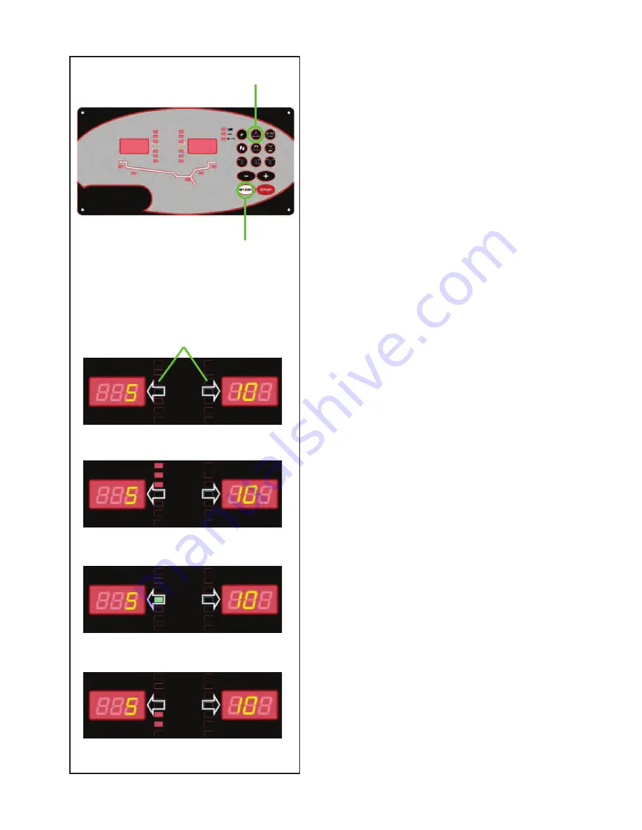
5.3.3-1
5.3.4-3
5.3.4-2
5.3.4-4
5.3.4-1
1
Operation
5.3.3
Spinning the Wheel
The wheel data must be acquired and the type of rim
to be used must be entered.
With Code C13 set on “
1
”;
• Close the wheel guard.
With Code C13 set on “
0
”;
• Close the wheel guard and press
START
.
The motor starts up and the wheel spins.
Wheels must turn towards the right, seen from the side
of the unit on which they are mounted.
The measurement is completed as soon as the
direction indicators light up. The unit beeps. The brake
will be applied automatically and the wheel will stop.
The weight(s) to be applied will be shown on the
display. For higher precision, select Fine (1, Figure
5.3.3-1).
•
Lift the wheel guard to its vertical position.
5.3.4
Weight application
The following weight types and application methods
are available:
- clip-on weights.
Always apply by hand.
- stick-on weights.
Must be applied by hand.
Note
:
Hand applied weights must always be
applied exactly perpendicular to the shaft
(12 o’clock position).
After spinning the wheel look at the rotation indicators
for the left plane of the wheel (1-Figure 5.3.4-1):
•
Slowly rotate the wheel manually (e.g. counter
clockwise) until the three top LEDs are on (1-Figure
5.3.4-2).
•
Continue with the rotation until all the LEDs switch
off progressively towards the centre.
Once the correct weight application position is reached,
only the green central LED is on Figure 5.3.4-3.
Note
:
At the correct angular position all rotation
indicators will be lit. If the wheel has been
rotated too far, only the indicators for the
other half will be lit. Refer to Figure 5.3.4-
4. The wheel has to be gently reversed.
2
1
Summary of Contents for Sun SWB 100
Page 90: ...90 Blank Page ...


