7
Series 100 UL
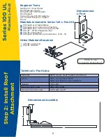
Flashed L-Foot
Design Tools
- SnapNrack has a suite of design tools
to help configure your PV installation to
be an accurate and fast install. Please
visit us at: www.SnapNrack.com.
Warning
- If a pilot hole is drilled and a rafter is not
found, immediately seal pilot hole with
roofing sealant to avoid water damage.
- Do not over tighten hardware.
- Always wear fall protection
and safety gear.
Notes
- Alternative 90° L Foot included
in UL 2703 Listing
- SnapNrack engineered systems should
only be used with SnapNrack components
and hardware. Any alternate application
may void the warranty and structural
calculations could become invalid.
Step-by-Step Instructions
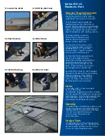
1) Locate the rafter underneath
the decking of the roof by looking
underneath the eaves or in the attic.
2) Drill a pilot hole through the
roofing material into the rafter to
ensure that the lag bolt will be located
into a solid portion of the rafter. If the
rafter is not found then seal the pilot
hole immediately with roofing sealant.
3) Apply roofing sealant to
the bottom of the base and
directly onto the lag bolt to
ensure a water tight seal.
4) Attach the L-foot base with
a 5/16” lag bolt and a minimum
embedment of 2 ½” lag shank
into the rafter. Tighten Lag bolt
to seat with a hand wrench.
5) Slide the flashing underneath
the row of shingles, directly
above the installed standard base,
and then line up the hole in the
flashing with the threads on the
base. It may be necessary to pry
up shingles with a breaker bar.
6) Attach the L-foot to the threaded
portion of the base that is protruding
from the flashing. Then tighten
the flange bolt over the threads
to 10 – 16 ft-lbs. The L-foot can
be attached in any orientation.
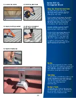
1) Locate the rafter
2) Drill the pilot hole
3) Prep the base
4) Attach base
5) Set the flashing
6) Attach L-Foot
Summary of Contents for Series 100 UL
Page 48: ...48 Notes...


