background image

5

Safery

Safety Rules and Information

Slope Operation

You could be seriously injured or even killed if you use this unit on too
steep an incline.  Using the unit on a slope that is too steep or where
you don’t have adequate traction can cause you to lose control or roll
over.

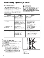
A good rule of thumb is to not operate on any slope you cannot back up
(in 2-wheel drive mode).  You should not operate on inclines with a
slope greater than a 3.5 foot rise over a 20 foot length.  Always drive up
and down slopes: never cross the face. 

Also note that the surface you are driving on can greatly impact stability
and control.  Wet grass or icy pavement can seriously affect your ability
to control the unit.

If you feel unsure about operating the unit on an incline, don’t do it.  It’s
not worth the risk.

Moving Parts

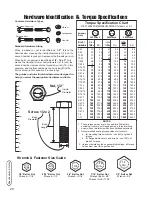
This equipment has many moving parts that can injure you or someone else.
However, if you are seated in the seat properly, and follow all the rules in this
book, the unit is safe to operate.  

Do not allow anyone near the equipment while it is running!  

To help you, the operator, use this equipment safely, it is equipped with an 
operator-present safety system.  Do NOT attempt to alter or bypass the system.
See your dealer immediately if the system does not pass all the safety interlock
system tests found in this manual.

Thrown Objects

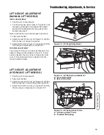
This unit has spinning mower blades.  These blades can pick up and throw
debris that could seriously injure a bystander.  Be sure to clean up the area to
be mowed BEFORE you start mowing.  

Do not operate this unit without the entire grass catcher or discharge guard
(deflector) in place.

Also, do not allow anyone in the area while the unit is running!  If someone
does enter the area, shut the unit off immediately until they leave.

Maintenance

Proper maintenance is critical to the safety and performance of your unit.
Be sure to perform the maintenance procedures listed in this manual,
especially periodically testing the safety system.

Summary of Contents for 1694151

Page 1: ...evision 04 Rev Date 06 2008 TP 100 2604 04 AT UV CAUTION Read and follow all instructions 36 Rotary Tiller Attachment for use with Conquest 1700 2700 Prestige 1800 2800 Snapper YT400 and GT500 Series...

Page 2: ...nstructions are not followed The information is for your safety and it is important The safety decals below are on your product If any decals are lost or damaged replace them at once See your local de...

Page 3: ...the Hitches 10 Install the Pulley Assemblies 11 Install the Rear Idler Pulley Assembly Select Models 11 Install the Lift Rod 12 Install the Tiller 13 Install the Belt 13 Adjustments 13 Operation 14 O...

Page 4: ...on of the product s features and controls and maintenance information is included to help you get the most out of your equipment investment Be sure to completely read the Safety Rules and Information...

Page 5: ...er if you are seated in the seat properly and follow all the rules in this book the unit is safe to operate Do not allow anyone near the equipment while it is running To help you the operator use this...

Page 6: ...mended by the manufacturer 7 Always wear safety glasses or eye shields during operation or while performing an adjustment or repair to protect eye from foreign objects that may be thrown from the mach...

Page 7: ...lace safety and instruction labels as necessary 6 Keep nuts and bolts tight and keep equipment in good condition 7 Never tamper with safety devices Check their proper operation regularly and make nece...

Page 8: ...achment raised back position 2 Loosen the manual lift adjustment bolt A Figure 2 until the bolt can be slid out of the groove in the bulkhead 3 Remove the pin A Figure 3 securing the lift link D 4 Rem...

Page 9: ...t Lock F Lift Lever G Locknut H Hair Pin Clip I Spacer J Lift Cam K Mower Hole Figure 4 Lift Components Tilling A Clevis Pin B 5 16 18 x 1 Capscrew Gr 5 C Washer D Lift Link New E Lift Lock F Lift Lev...

Page 10: ...ts J 3 Secure the sides of the hitch support C using four 3 8 16 x 1 capscrews D and four 3 8 16 nylock nuts B D B A C C B E Figure 6 Rear Hitch Installation A 1 2 13 x 2 Capscrew B Washer C Spacer D...

Page 11: ...haft C 3 Hook the slot D onto the tractor frame as shown in Figure 9 Figure 8 Front Idler Pulley Installation A Idler Pulley Assembly B Left Stub C Lift Assembly Cross shaft D Slot Figure 9 Front Idle...

Page 12: ...ght stub at the end of the lift assembly cross shaft Secure with a clevis pin and hair pin clip see Figure 12 inset MANUAL LIFT MODELS ONLY 3 Mount the front bracket D Figure 11 to the frame using a 5...

Page 13: ...tall the Belt 1 Remove the spring clip and pin securing the tiller belt cover Pivot the belt cover out of the way to allow access to the tiller pulleys 2 Install the belt on the rear pulley assembly C...

Page 14: ...und in your tractor Operator s Manual If tractor does not pass the test do not operate the tractor See your authorized dealer Under no circumstances should you attempt to defeat the safety system To p...

Page 15: ...NG To avoid serious injury perform maintenance on the tiller only when the engine is stopped parking brake is set and all moving parts have stopped Always remove the ignition key before beginning main...

Page 16: ...the mowing position C 1 Manual Lift Models Switch the lift link from mowing position C Figure 20 to tilling position D 2 Attach the tiller to the rear hitch see Figure 19 3 Install the lift bracket A...

Page 17: ...Threaded Rod Spring C Lift Rod A B C Figure 18 Lift Arm Extension A Lift Bracket A C D A B Figure 19 Tiller Assembly A Lift Bar B Upper Hitch C Hitch Arm D Lower Hitch Figure 20 Lift Link Positions N...

Page 18: ...too hard 1 Adjust the attachment lift 2 Set engine to full speed 3 Slow down 4 Make several passes tilling deeper on each pass Tiller leaves ground rough with large clods 1 Ground too wet 2 Tilling to...

Page 19: ...th of 9 WORKING ADJUSTMENT The amount of lift assist can be varied based on the depth of tilling and the hardness of the soil If more assist is desired the turn crank A Figure 24 clock wise If more do...

Page 20: ...s self tapping screws thread forming screws sheet metal screws and socket head setscrews 2 Recommended seating torque values for locknuts a for prevailing torque locknuts use 65 of grade 5 torques b f...

Page 21: ...21 Notes NOTES...

Page 22: ...n com Briggs Stratton Power Products Group L L C Copyright 2008 Briggs Stratton Corporation Milwaukee WI USA All Rights Reserved www BRIGGSandSTRATTON com www MasseyLawn com www snapper com www simpli...

Reviews: