background image

17

Initial Setup & Assembly

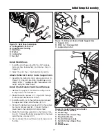
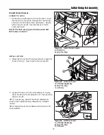
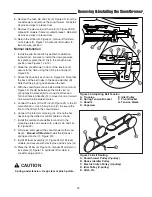
Figure 18.  Skid Shoe Installation
A. Carriage Bolt, 3/8-16 x 3/4”
B. Snowthrower Housing
C. Skid Shoe
D. Washer
E. Lockwasher
F. Hex Nut

A

B

C

D

E

F

Install Skid Shoes

1. Install the skid shoes using 3/8-16 x 3/4” carriage

bolts, washers, lockwashers, and nuts as shown in
Figure 18.  

2. Adjust the skid shoes.  See Adjustments section.

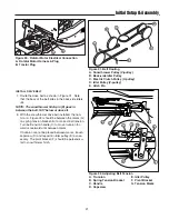
Attach Deflector Control Cable Support Arm

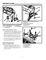
1. Assemble the deflector control cable support arm (A,

Figure 19) to the left side of the snowthrower using
one 5/16-18 x 1” carriage bolt (B), lockwasher, and
nut (C) using the holes shown.

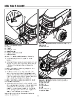
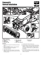
Install Chute Rotator Switch and Harness

1. Remove the plug from the switch mounting hole in

the right side of the dashboard.

2. Route the switch harness (C, F, Figure 20) through

the frame and dashboard as shown.

3. Install the switch (G) in the dashboard and connect

the upper end of the switch harness (F) to it.

4. Connect the red/yellow power lead (H) to the red/yel-

low tractor harness lead (E).  Connect the black
power lead to the black tractor harness lead.

5. Mount the trailer plug socket (B) in the frame at loca-

tion (D).  Connect the trailer plug lead (B) to the lower
switch harness connector (C).

6. Do not connect the snowthrower wire harness (A) at

this time.  

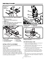
Figure 20.  Install Power Port & Switch
A. Rotator Motor Harness
B. Trailer Plug
C. Switch Harness Lower Plug
D. Plug Hole (Frame)
E. Tractor Harness Leads
F. Switch Harness Upper Plug
G. Switch
H. Power Leads

G

A

B

F

H

E

C

D

B

A

Figure 19.  Deflector Control Cable Support Arm
A. Support Arm
B. 5/16-18 x 1 Carriage Bolt
C. Lockwasher & Nut

C

Summary of Contents for 1694238

Page 1: ...L 42 Snowthrower Attachment Mfg No Description 1694238 42 Two Stage Snowthrower 1694874 42 Two Stage Snowthrower 1695099 42 Two Stage Snowthrower 42 Two Stage Snowthrower 1724089 Revision 10 Rev Date 6 2006 TP 100 3605 10 AT SMA ...

Page 2: ......

Page 3: ...ents 24 Hardware Torque Specifications Chart 25 Mounting Remote Deflector Control Instructions 26 Template 27 Recommended Accessories 1 Safety Rules Information Training 2 Preparation 2 Operation 2 Children 3 Clearing a Clogged Discharge Chute 3 Service Maintenance and Storage 3 Emissions 3 Decals 4 Required Accessories 5 Recommended Accessories 5 Clean Out Warning and Procedure 5 Features Control...

Page 4: ...s wear safety glasses or eye shields during operation or while performing an adjustment or repair to protect eye from foreign objects that may be thrown from the machine OPERATION 1 Do not put hands or feet near or under rotating parts Keep clear of the discharge opening at all times 2 Exercise extreme caution when operating on or crossing gravel drives walks or roads Stay alert for hidden hazards...

Page 5: ...other people or property 22 Data indicates that operators age 60 years and above are involved in a large percentage of power equipment related injuries These operators should evaluate their ability to operate the unit safely enough to protect themselves and others from injury 23 DO NOT wear long scarves or loose clothing that could become entangled in moving parts 24 Snow can hide obstacles Make s...

Page 6: ...basic knowledge to operate this equipment safely and effec tively we have placed several safety labels on the unit to remind you of this important information while you are operating your unit All DANGER WARNING CAUTION and instructional messages on your unit should be carefully read and obeyed Personal bodily injury can result when these instructions are not followed The information is for your s...

Page 7: ...ered by this manual and must be installed as part of hitch installation TRACTOR CONTROLS Before you begin operating the tractor and attachment make certain you have Read and understood the instructions in the tractor Operator s Manual Become thoroughly familiar with all of the trac tor controls and their operation including how to safely and properly start and stop the unit Practice driving in an ...

Page 8: ...s and lowers the attach ment To RAISE an attachment depress the release button on top of the lever and pull back To LOWER an attachment depress the release button and move the lever forward When lowering the attachment be sure to push the lever fully forward into the locked position E Deflector Control The deflector control changes the angle of the snowthrower discharge deflector Twist the handle ...

Page 9: ... Operator s Manual If tractor does not pass the test do not operate the tractor See your authorized dealer Under no circumstances should you attempt to defeat the safety system Use caution when clearing a snow covered area Snow can cover objects such as curbs drop offs and other obstacles Be familiar with the area you are clearing To prevent an explosion or fire never store the tractor with fuel i...

Page 10: ... If snow stops flowing freely from the spout back away until the snowthrower clears itself Daily Storage 1 Run the snowthrower a few minutes after blowing snow to prevent freeze up of auger 2 Allow tractor engine to cool before storing in any enclosure Off Season Storage 1 Remove snowthrower from the tractor 2 Use water pressure or a brush to thoroughly clean the housing 3 Paint or lightly coat wi...

Page 11: ... pivot points Grease the auger bearings Grease the the auger shaft grease fittings WARNING To avoid serious injury perform maintenance on the unit only when the engine is stopped and all moving parts have stopped Always remove the ignition key before beginning maintenance or adjustments to prevent accidental starting of the engine Figure 2 Lubrication Points Care Required Schedule Clean snow and i...

Page 12: ...g A Figure 4 Impeller Gear Box Oil A Fill Plug A Check the Impeller Gear Box Oil Level Perform this check every season The gear box oil capacity is 12 oz The gear box can be accessed from the rear of the snowthrower attachment 1 Remove the oil fill plug A Figure 4 from the top of the gear box 2 Insert a piece of wire into the gear box to check the oil level 3 Add 85W 90 gear lube oil if required T...

Page 13: ... required 2 Auger does not stop when A Electric clutch brake not operating properly See your dealer electric clutch is disengaged 3 Auger rotates but snow A Engine RPM too slow Set throttle to FULL is not thrown far enough B Ground speed too fast Use slow ground speed C Snowthrower discharge chute clogged STOP engine Remove key Unplug discharge chute using a piece of wood Read WARNING on page 5 D ...

Page 14: ...tric spout rotator motor 2 Adjust the motor so that it meshes with the discharge chute ring gear and tighten the adjustment screws A 3 Reinstall the cover Auger Shear Pins The auger shear pins A Figure 8 are designed to break if the auger strikes an object Replace the shear pins with original factory specification shear pins ONLY Impeller Shear Bolt The impeller shear bolt is designed to break if ...

Page 15: ...nd adjust the front set collar A Figure 9 to achieve the correct lift height DOWNWARD PRESSURE ADJUSTMENT NOTE Check that the lift bar or lock plate Figures 14 15 are in the correct positions 1 Place the lift in the fully raised position 2 Release the rear set collar C Figure 9 3 Slide the set collar C forward until it is slightly com pressing the spring Tighten the set collar screw Do not over co...

Page 16: ...ey D Snowthrower Pulley V pulley E Idler Pulley A D B C E Figure 11 Adjusting Belt Tension A Trunnion E Idler Pulley B Spring Tension Bracket F Pivot Bracket C Handle G Tension Marks D Capscrew Belt Tension Adjustment 1 With the snowthrower drive belt installed trunnion A Figure 11 should be between marks G on spring tension bracket B for correct belt tension 2 Turn belt tension handle C to move t...

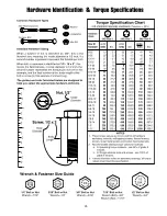
Page 17: ...Qty Description 12 1 SWITCH 13 1 WIRE HARNESS Switch 14 1 WIRE HARNESS Trailer Plug 15 1 SUPPORT 16 1 CARRIAGE BOLT 5 16 18 x 1 17 2 HAIR PIN CLIP 18 2 ROD Latch 19 1 NUT 5 16 18 20 1 LOCKWASHER 5 16 21 1 NUT 5 16 18 22 1 LOCKWASHER 5 16 Ref Qty Description 23 1 WASHER Over size 24 1 CAPSCREW 5 16 18 x 1 25 1 BRACKET Spring Anchor 26 1 CAPSCREW 5 16 18 x 4 1 2 27 1 SPRING RETAINER 28 1 NUT Cage 29...

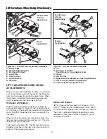
Page 18: ...Head Pin Original E Hair Pin Clips C Flat Head Pin New F Lift Shaft Assy A B C D F E A B C D E Figure 14 Connect Lift Link Manual Lift Models A Pin B Rear Hole of Lift Bar Snowthrower Dozer Applications C Spacer D Hair Pin Clip E Upper Hole Snowthrower Dozer Applications F Slot of Lift Link Mower Applications G Lower Hole Mower Applications Snowthrower Dozer Applications Assemble Discharge Chute 1...

Page 19: ...ight side of the dashboard 2 Route the switch harness C F Figure 20 through the frame and dashboard as shown 3 Install the switch G in the dashboard and connect the upper end of the switch harness F to it 4 Connect the red yellow power lead H to the red yel low tractor harness lead E Connect the black power lead to the black tractor harness lead 5 Mount the trailer plug socket B in the frame at lo...

Page 20: ... large flat washers B 3 Install the remote deflector control handle B Figure 22 in the mounting bracket C and secure with a clevis pin A and hair pin clip D Mount Lift Assist Bracket Manual Lift Models Only 1 Mount the lift assist bracket A Figure 233 to the snowthrower Slide the bracket back so that it engages the snowthrower housing Secure using a 5 16 18 x 1 capscrew B large washer C lock washe...

Page 21: ... the snowthrower Secure with a hair pin clip B Use the back set of hitch holes see inset NOTE The hitch pin A goes in between the belt NOT below or above it B A INSTALL LIFT ROD 2 Attach the front of the lift rod assembly A Figure 25 to the lift arm C Secure with a hair pin clip B A B C A B C 3 Connect the rear of the lift rod assembly A Figure 26 to the tractor lift arm extension C Secure with a ...

Page 22: ... CONNECT ELECTRICAL HARNESS UNITS WITH RIGHT SIDE MOUNTED MOTORS 6 Raise the hood and route the wire harness A Figure 29 along the edge of the frame Connect wire tie B loosely around the wire harness A and engine shield C Route the wire harness A through the lowest opening in grill as shown Slide clip D onto hole E Place harness A into clip D Note Leave the wire tie B loose to aid in seasonal remo...

Page 23: ...DRIVE BELT 7 Route the drive belt as shown in Figure 31 Note that the back of the belt rides in the back side idlers B NOTE The snowthrower hitch pin E goes in between the belt NOT below or above it 8 With the snowthrower drive belt installed the trun nion A Figure 32 should be between the marks G on spring tension bracket B for correct belt tension Turn belt tension handle C to move trunnion for ...

Page 24: ... motor plug A 6 Disconnect the rear of the lift rod B from the lift arm extension Remove the hair pin clip C from the front of the lift rod Remove the lift rod Remove the lift arm extension from the tractor see Hitch Installation Instructions 7 Use the trunnion handle C Figure 34 to relieve belt tension Remove the belt from the snowthrower drive pulley A Figure 35 A C D B E F G G H Figure 33 Remov...

Page 25: ...Note that the pin E goes between the belt 4 With the snowthrower drive belt installed trunnion A Figure 34 should be between the marks G on spring tension bracket B for correct belt tension Turn belt tension handle C to move trunnion forward or rearward until between marks 5 Connect the rear of the lift rod B Figure 33 to the lift arm extension Use a hair pin clip C to secure the front of the lift...

Page 26: ...nstalled the downward pressure lock must be released so that the mower can float Hydraulic Lift Models When using a snowthrower or dozer the downward pressure lock plate D Figure 36 and an additional pin C is installed These parts are included with the attach ment Note that the washers G are not used with the lock plate When mowing the downward pressure lock plate D is removed and replaced with tw...

Page 27: ...25 ...

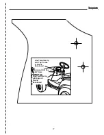
Page 28: ...8 control to the dashboard using upper hole 5 Align center of lower hole to dashed line on template and mark Remove the remote deflector mounting bracket E Drill one 9 32 hole using the marked location 6 Mount the remote deflector mounting bracket E con trol to the dashboard Secure using two 1 4 20 x 7 8 capscrews A through the bracket E and dash board 7 Secure with 1 4 x 1 1 4 flatwashers B lockw...

Page 29: ...27 Template Line Template Up with Top Crease of Plastic Dashboard Line Template Up with Edge of Plastic Dashboard Mark and Drill One 9 32 Hole ...

Page 30: ...C 500 N Spring Street PO Box 997 Port Washington WI 53074 0997 www SimplicityMfg com 500 N Spring Street PO Box 997 Port Washington WI 53074 0997 AGCOLawn com PRODUCTS 535 Macon Street McDonough GA 30253 www Snapper com Copyright 2006 Simplicity Manufacturing Inc All Rights Reserved Printed in USA ...

Reviews: