background image

Summary of Contents for 1694888

Page 1: ...4 20HP 44 Mower Deck ELT2044 20HP 44 Mower Deck CE LT2042 20HP 42 Mower Deck LT2044 20HP 44 Mower Deck ELT2044 20HP 44 Mower Deck CE 22HP Hydro Tractors Mfg No Description 2690443 LT2250 22HP 50 Mower...

Page 2: ...Check 18 PTO Clutch Adjustment Check 18 Engine Maintenance 18 Battery Maintenance 18 Transmission Identification 19 Transmission Maintenance 19 Hood Removal and Installation 19 Lubrication 20 Lubrica...

Page 3: ...uct s features and controls and maintenance information is included to help you get the most out of your equipment investment Be sure to completely read the Safety Rules and Information found on the f...

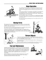
Page 4: ...s equipment safely it is equipped with an operator present safety system Do NOT attempt to alter or bypass the system See your dealer immediately if the system does not pass all the safety interlock s...

Page 5: ...uries These operators should evaluate their ability to operate the equipment safely enough to protect themselves and others from injury 19 Follow the manufacturer s recommendations for wheel weights o...

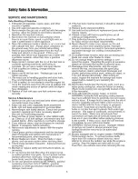
Page 6: ...nd gradually downhill if possible TOWED EQUIPMENT RIDE ON UNITS 1 Tow only with a machine that has a hitch designed for towing Do not attach towed equipment except at the hitch point 2 Follow the manu...

Page 7: ...may ignite Do not spread fuel line clamps further than necessary Ensure clamps grip hoses firmly over the filter after installation 12 Do not use gasoline containing METHANOL gasohol containing more t...

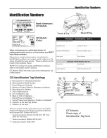
Page 8: ...SERIAL Number Mower Deck SERIAL Number Date Purchased Engine Make Engine Model Engine Type Spec Engine C0de Serial Number CE Identification Tag Markings A Manufacturer s identification Number B Manuf...

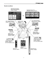
Page 9: ...ety decals below are on your rider and mower If any of these decals are lost or damaged replace them at once See your local dealer for replacements These labels are easily applied and will act as a co...

Page 10: ...ignition Switch Positions Part No 1722806 CE Danger Rotating Blades Part No 1720389 OR Danger Side Discharge Models Part No 1704276 OR Danger Side Discharge Models Part No 1704277 Caution Pinch Point...

Page 11: ...ION section _JI _ lP__Throttle Control The throttle controls engine speed Move the throttle forward to increase engine speed and back to decrease engine speed Always operate at FULL throttle _ Choke C...

Page 12: ...d control pedal Depressing either pedal will increase ground speed Note that the further down the pedal is depressed the faster the tractor will travel _D Cruise Control The cruise control is used to...

Page 13: ...A Hourrneter Select Models The hour meter E Figure 2 measures the number of hours the key has been in the RUN position Figure 2 Engaging the Parking Brake A Ground Speed Pedals B Brake Pedal C Parking...

Page 14: ...t operate it See your authorized dealer Under no circumstance should you attempt to defeat the purpose of the safety interlock system General Operating Safety Be sure to read all information in the Sa...

Page 15: ...off if the reverse ground speed pedal is depressed while the PTO is on and the RMO has not been activated The operator should always turn the PTO off prior to driving across on roads paths or any area...

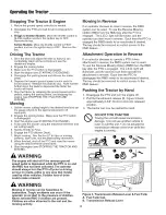
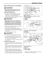
Page 16: ...r to highest position CAUTION The muffler and surrounding areas may be hot 6 Turn wheels straight ahead Support the mower hanger C Remove safety clip A Figure 6 and rod B Lower the mower hanger C 7 Tu...

Page 17: ...nit for the off season read the Maintenance and Storage instructions inthe Safety Rules section then perform the following steps Disengage the PTO set the parking brake remove the key Perform engine m...

Page 18: ...MAINTENANCE iTEMS Before Every 5 Every Every Every Spring Each Hours 25 50 100 Fall Use Hours Hours Hours Check Engine Oil Level e Check Change Engine Air Filter e Change Engine Oil e e e Change Engi...

Page 19: ...stments section of this manual Engine Maintenance Refer to the engine owner s manual for all engine maintenance procedures and recommendations Battery Maintenance WARNING When removing or installing b...

Page 20: ...installation HOOD REMOVAL 1 Open the hood 2 Remove the socket and bulbs A Figure 12 by twisting the socket counterclockwise and pulling it out of the bezel B Repeat on other side 3 Rock the hood back...

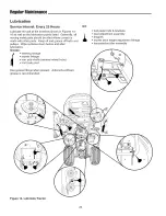
Page 21: ...de with other parts Keep oil and grease off belts and pulleys Wipe surfaces clean before and after lubrication Grease steering linkage mower linkage rear axle shafts remove wheel hubs front axle pivot...

Page 22: ...2 2 5 5cm off the ground NOTE For overall unit stability during service do not jack rear end higher than required for wheel removal 3 Support the rear of the unit on jackstands positioned under the re...

Page 23: ...D Figure 21 hex washer B spring washer C and blade 4 Use a file to sharpen blade to a fine edge If blade is damaged it must be replaced 5 Balance the blade as shown in Figure 18 Center the blade s ho...

Page 24: ...ngine Briggs Stratton Models thread the cap back onto the tube Kohler Models push cap C firmly into place 5 Remove the dip stick and read the oil level The oil level should be between the FULL and ADD...

Page 25: ...urs or once per season Oil Capacity Approximately 2 quarts 1 9L with oil filter change NOTE Change engine oil while the engine is warm Run the engine for a few minutes then shut the engine off and all...

Page 26: ...r slots Secure by turning screws clockwise until snug Pre Cleaner Service NOTE Replace a worn or damaged pre cleaner 1 Figure 27 Wash the pre cleaner in liquid detergent and water 2 Squeeze the pre cl...

Page 27: ...e the tabs are inserted into their slots Secure with the latch A Pre Cleaner Service NOTE Replace a worn or damaged pre cleaner 1 Figure 28 Wash the pre cleaner in liquid detergent and water 2 Squeeze...

Page 28: ...RC12YC 1 Stop the engine and allow it to cool 2 See Figures 31or 32 Clean the area around the spark plug 3 Remove the spark plug 4 Check the spark plug gap It should be 030 see Figure 31 or 32 5 Reins...

Page 29: ...sumption 1 2 3 Engine exhaust is black 1 2 Engine runs but tractor will 1 not drive 0 1 2 3 4 Solenoid or starter motor faulty Safety interlock switch faulty Spark plug s faulty fouled or incorrectly...

Page 30: ...bration Excessive belt wear or breakage Mower drive belt slips or fails to drive 4 Mower drive belt slipping because it is oily or worn 5 Check PTO Electric Clutch Adjustment 6 Blades not properly fas...

Page 31: ...arging system or other electrical component If there is any doubt about the cause of the problem see your dealer If you need to replace the battery follow the steps under Cleaning the Battery Cables i...

Page 32: ...ately tighten the adjustment nuts B Figure 34 until the rotor face and armature face just contacts the gauge 5 Check the windows for an equal amount of tension when the gauge is inserted and removed a...

Page 33: ...nk Broken Fusible Link Mower Adjustments Gauge Wheels Select Models The mower gauge wheels can be placed in two positions depending on the height of cut When using higher cutting heights set the wheel...

Page 34: ...ut B Figure 39 to raise or lower that side of the mower Note The maximum the mower can be adjusted in high cut is 3 8 to 1 2 between the frame and mower up stop See Figure 39 FRONT TO BACK LEVELING 6...

Page 35: ...dels Loosen the belt stop bracket s C 5 Remove the old belt and replace with a new belt Make sure V side of belt runs in arbor pulley grooves and the flat backside runs against the idler pulley 6 Some...

Page 36: ...DIMENSIONS LT Series Overall Length 72 Overall Width 37 Height 45 Weight 18 5h p Tractor w 38 Mower Deck 480 Ibs 218 kg 20hp Tractor w 42 Mower Deck 494 Ibs 224 kg 20hp Tractor w 44 Mower Deck 532 Ib...

Page 37: ...ly illustrated parts lists These manuals show all of the product s components in exploded views 3D illustrations which show the relationship of parts and how they go together as well as part numbers a...

Page 38: ...Snapper INC 535 Macon Street McDonough GA 30253 www snapper com Briggs Stratton Yard Power Products Group Copyright 2006 Briggs Stratton Corporation Milwaukee WI USA All Rights Reserved...

Page 39: ...4 20HP 44 Mower Deck ELT2044 20HP 44 Mower Deck CE LT2042 20HP 42 Mower Deck LT2044 20HP 44 Mower Deck ELT2044 20HP 44 Mower Deck CE 22HP Hydro Tractors Mfg No Description 2690443 LT2250 22HP 50 Mower...

Page 40: ...Check 18 PTO Clutch Adjustment Check 18 Engine Maintenance 18 Battery Maintenance 18 Transmission Identification 19 Transmission Maintenance 19 Hood Removal and Installation 19 Lubrication 20 Lubrica...

Page 41: ...uct s features and controls and maintenance information is included to help you get the most out of your equipment investment Be sure to completely read the Safety Rules and Information found on the f...

Page 42: ...s equipment safely it is equipped with an operator present safety system Do NOT attempt to alter or bypass the system See your dealer immediately if the system does not pass all the safety interlock s...

Page 43: ...uries These operators should evaluate their ability to operate the equipment safely enough to protect themselves and others from injury 19 Follow the manufacturer s recommendations for wheel weights o...

Page 44: ...nd gradually downhill if possible TOWED EQUIPMENT RIDE ON UNITS 1 Tow only with a machine that has a hitch designed for towing Do not attach towed equipment except at the hitch point 2 Follow the manu...

Page 45: ...may ignite Do not spread fuel line clamps further than necessary Ensure clamps grip hoses firmly over the filter after installation 12 Do not use gasoline containing METHANOL gasohol containing more t...

Page 46: ...SERIAL Number Mower Deck SERIAL Number Date Purchased Engine Make Engine Model Engine Type Spec Engine C0de Serial Number CE Identification Tag Markings A Manufacturer s identification Number B Manuf...

Page 47: ...ety decals below are on your rider and mower If any of these decals are lost or damaged replace them at once See your local dealer for replacements These labels are easily applied and will act as a co...

Page 48: ...ignition Switch Positions Part No 1722806 CE Danger Rotating Blades Part No 1720389 OR Danger Side Discharge Models Part No 1704276 OR Danger Side Discharge Models Part No 1704277 Caution Pinch Point...

Page 49: ...ION section _JI _ lP__Throttle Control The throttle controls engine speed Move the throttle forward to increase engine speed and back to decrease engine speed Always operate at FULL throttle _ Choke C...

Page 50: ...d control pedal Depressing either pedal will increase ground speed Note that the further down the pedal is depressed the faster the tractor will travel _D Cruise Control The cruise control is used to...

Page 51: ...A Hourrneter Select Models The hour meter E Figure 2 measures the number of hours the key has been in the RUN position Figure 2 Engaging the Parking Brake A Ground Speed Pedals B Brake Pedal C Parking...

Page 52: ...t operate it See your authorized dealer Under no circumstance should you attempt to defeat the purpose of the safety interlock system General Operating Safety Be sure to read all information in the Sa...

Page 53: ...off if the reverse ground speed pedal is depressed while the PTO is on and the RMO has not been activated The operator should always turn the PTO off prior to driving across on roads paths or any area...

Page 54: ...r to highest position CAUTION The muffler and surrounding areas may be hot 6 Turn wheels straight ahead Support the mower hanger C Remove safety clip A Figure 6 and rod B Lower the mower hanger C 7 Tu...

Page 55: ...nit for the off season read the Maintenance and Storage instructions inthe Safety Rules section then perform the following steps Disengage the PTO set the parking brake remove the key Perform engine m...

Page 56: ...MAINTENANCE iTEMS Before Every 5 Every Every Every Spring Each Hours 25 50 100 Fall Use Hours Hours Hours Check Engine Oil Level e Check Change Engine Air Filter e Change Engine Oil e e e Change Engi...

Page 57: ...stments section of this manual Engine Maintenance Refer to the engine owner s manual for all engine maintenance procedures and recommendations Battery Maintenance WARNING When removing or installing b...

Page 58: ...installation HOOD REMOVAL 1 Open the hood 2 Remove the socket and bulbs A Figure 12 by twisting the socket counterclockwise and pulling it out of the bezel B Repeat on other side 3 Rock the hood back...

Page 59: ...de with other parts Keep oil and grease off belts and pulleys Wipe surfaces clean before and after lubrication Grease steering linkage mower linkage rear axle shafts remove wheel hubs front axle pivot...

Page 60: ...2 2 5 5cm off the ground NOTE For overall unit stability during service do not jack rear end higher than required for wheel removal 3 Support the rear of the unit on jackstands positioned under the re...

Page 61: ...D Figure 21 hex washer B spring washer C and blade 4 Use a file to sharpen blade to a fine edge If blade is damaged it must be replaced 5 Balance the blade as shown in Figure 18 Center the blade s ho...

Page 62: ...ngine Briggs Stratton Models thread the cap back onto the tube Kohler Models push cap C firmly into place 5 Remove the dip stick and read the oil level The oil level should be between the FULL and ADD...

Page 63: ...urs or once per season Oil Capacity Approximately 2 quarts 1 9L with oil filter change NOTE Change engine oil while the engine is warm Run the engine for a few minutes then shut the engine off and all...

Page 64: ...r slots Secure by turning screws clockwise until snug Pre Cleaner Service NOTE Replace a worn or damaged pre cleaner 1 Figure 27 Wash the pre cleaner in liquid detergent and water 2 Squeeze the pre cl...

Page 65: ...e the tabs are inserted into their slots Secure with the latch A Pre Cleaner Service NOTE Replace a worn or damaged pre cleaner 1 Figure 28 Wash the pre cleaner in liquid detergent and water 2 Squeeze...

Page 66: ...RC12YC 1 Stop the engine and allow it to cool 2 See Figures 31or 32 Clean the area around the spark plug 3 Remove the spark plug 4 Check the spark plug gap It should be 030 see Figure 31 or 32 5 Reins...

Page 67: ...sumption 1 2 3 Engine exhaust is black 1 2 Engine runs but tractor will 1 not drive 0 1 2 3 4 Solenoid or starter motor faulty Safety interlock switch faulty Spark plug s faulty fouled or incorrectly...

Page 68: ...bration Excessive belt wear or breakage Mower drive belt slips or fails to drive 4 Mower drive belt slipping because it is oily or worn 5 Check PTO Electric Clutch Adjustment 6 Blades not properly fas...

Page 69: ...arging system or other electrical component If there is any doubt about the cause of the problem see your dealer If you need to replace the battery follow the steps under Cleaning the Battery Cables i...

Page 70: ...ately tighten the adjustment nuts B Figure 34 until the rotor face and armature face just contacts the gauge 5 Check the windows for an equal amount of tension when the gauge is inserted and removed a...

Page 71: ...nk Broken Fusible Link Mower Adjustments Gauge Wheels Select Models The mower gauge wheels can be placed in two positions depending on the height of cut When using higher cutting heights set the wheel...

Page 72: ...ut B Figure 39 to raise or lower that side of the mower Note The maximum the mower can be adjusted in high cut is 3 8 to 1 2 between the frame and mower up stop See Figure 39 FRONT TO BACK LEVELING 6...

Page 73: ...dels Loosen the belt stop bracket s C 5 Remove the old belt and replace with a new belt Make sure V side of belt runs in arbor pulley grooves and the flat backside runs against the idler pulley 6 Some...

Page 74: ...DIMENSIONS LT Series Overall Length 72 Overall Width 37 Height 45 Weight 18 5h p Tractor w 38 Mower Deck 480 Ibs 218 kg 20hp Tractor w 42 Mower Deck 494 Ibs 224 kg 20hp Tractor w 44 Mower Deck 532 Ib...

Page 75: ...ly illustrated parts lists These manuals show all of the product s components in exploded views 3D illustrations which show the relationship of parts and how they go together as well as part numbers a...

Page 76: ...Snapper INC 535 Macon Street McDonough GA 30253 www snapper com Briggs Stratton Yard Power Products Group Copyright 2006 Briggs Stratton Corporation Milwaukee WI USA All Rights Reserved...

Page 77: ...4 20HP 44 Mower Deck ELT2044 20HP 44 Mower Deck CE LT2042 20HP 42 Mower Deck LT2044 20HP 44 Mower Deck ELT2044 20HP 44 Mower Deck CE 22HP Hydro Tractors Mfg No Description 2690443 LT2250 22HP 50 Mower...

Page 78: ...Check 18 PTO Clutch Adjustment Check 18 Engine Maintenance 18 Battery Maintenance 18 Transmission Identification 19 Transmission Maintenance 19 Hood Removal and Installation 19 Lubrication 20 Lubrica...

Page 79: ...uct s features and controls and maintenance information is included to help you get the most out of your equipment investment Be sure to completely read the Safety Rules and Information found on the f...

Page 80: ...s equipment safely it is equipped with an operator present safety system Do NOT attempt to alter or bypass the system See your dealer immediately if the system does not pass all the safety interlock s...

Page 81: ...uries These operators should evaluate their ability to operate the equipment safely enough to protect themselves and others from injury 19 Follow the manufacturer s recommendations for wheel weights o...

Page 82: ...nd gradually downhill if possible TOWED EQUIPMENT RIDE ON UNITS 1 Tow only with a machine that has a hitch designed for towing Do not attach towed equipment except at the hitch point 2 Follow the manu...

Page 83: ...may ignite Do not spread fuel line clamps further than necessary Ensure clamps grip hoses firmly over the filter after installation 12 Do not use gasoline containing METHANOL gasohol containing more t...

Page 84: ...SERIAL Number Mower Deck SERIAL Number Date Purchased Engine Make Engine Model Engine Type Spec Engine C0de Serial Number CE Identification Tag Markings A Manufacturer s identification Number B Manuf...

Page 85: ...ety decals below are on your rider and mower If any of these decals are lost or damaged replace them at once See your local dealer for replacements These labels are easily applied and will act as a co...

Page 86: ...ignition Switch Positions Part No 1722806 CE Danger Rotating Blades Part No 1720389 OR Danger Side Discharge Models Part No 1704276 OR Danger Side Discharge Models Part No 1704277 Caution Pinch Point...

Page 87: ...ION section _JI _ lP__Throttle Control The throttle controls engine speed Move the throttle forward to increase engine speed and back to decrease engine speed Always operate at FULL throttle _ Choke C...

Page 88: ...d control pedal Depressing either pedal will increase ground speed Note that the further down the pedal is depressed the faster the tractor will travel _D Cruise Control The cruise control is used to...

Page 89: ...A Hourrneter Select Models The hour meter E Figure 2 measures the number of hours the key has been in the RUN position Figure 2 Engaging the Parking Brake A Ground Speed Pedals B Brake Pedal C Parking...

Page 90: ...t operate it See your authorized dealer Under no circumstance should you attempt to defeat the purpose of the safety interlock system General Operating Safety Be sure to read all information in the Sa...

Page 91: ...off if the reverse ground speed pedal is depressed while the PTO is on and the RMO has not been activated The operator should always turn the PTO off prior to driving across on roads paths or any area...

Page 92: ...r to highest position CAUTION The muffler and surrounding areas may be hot 6 Turn wheels straight ahead Support the mower hanger C Remove safety clip A Figure 6 and rod B Lower the mower hanger C 7 Tu...

Page 93: ...nit for the off season read the Maintenance and Storage instructions inthe Safety Rules section then perform the following steps Disengage the PTO set the parking brake remove the key Perform engine m...

Page 94: ...MAINTENANCE iTEMS Before Every 5 Every Every Every Spring Each Hours 25 50 100 Fall Use Hours Hours Hours Check Engine Oil Level e Check Change Engine Air Filter e Change Engine Oil e e e Change Engi...

Page 95: ...stments section of this manual Engine Maintenance Refer to the engine owner s manual for all engine maintenance procedures and recommendations Battery Maintenance WARNING When removing or installing b...

Page 96: ...installation HOOD REMOVAL 1 Open the hood 2 Remove the socket and bulbs A Figure 12 by twisting the socket counterclockwise and pulling it out of the bezel B Repeat on other side 3 Rock the hood back...

Page 97: ...de with other parts Keep oil and grease off belts and pulleys Wipe surfaces clean before and after lubrication Grease steering linkage mower linkage rear axle shafts remove wheel hubs front axle pivot...

Page 98: ...2 2 5 5cm off the ground NOTE For overall unit stability during service do not jack rear end higher than required for wheel removal 3 Support the rear of the unit on jackstands positioned under the re...

Page 99: ...D Figure 21 hex washer B spring washer C and blade 4 Use a file to sharpen blade to a fine edge If blade is damaged it must be replaced 5 Balance the blade as shown in Figure 18 Center the blade s ho...

Page 100: ...ngine Briggs Stratton Models thread the cap back onto the tube Kohler Models push cap C firmly into place 5 Remove the dip stick and read the oil level The oil level should be between the FULL and ADD...

Page 101: ...urs or once per season Oil Capacity Approximately 2 quarts 1 9L with oil filter change NOTE Change engine oil while the engine is warm Run the engine for a few minutes then shut the engine off and all...

Page 102: ...r slots Secure by turning screws clockwise until snug Pre Cleaner Service NOTE Replace a worn or damaged pre cleaner 1 Figure 27 Wash the pre cleaner in liquid detergent and water 2 Squeeze the pre cl...

Page 103: ...e the tabs are inserted into their slots Secure with the latch A Pre Cleaner Service NOTE Replace a worn or damaged pre cleaner 1 Figure 28 Wash the pre cleaner in liquid detergent and water 2 Squeeze...

Page 104: ...RC12YC 1 Stop the engine and allow it to cool 2 See Figures 31or 32 Clean the area around the spark plug 3 Remove the spark plug 4 Check the spark plug gap It should be 030 see Figure 31 or 32 5 Reins...

Page 105: ...sumption 1 2 3 Engine exhaust is black 1 2 Engine runs but tractor will 1 not drive 0 1 2 3 4 Solenoid or starter motor faulty Safety interlock switch faulty Spark plug s faulty fouled or incorrectly...

Page 106: ...bration Excessive belt wear or breakage Mower drive belt slips or fails to drive 4 Mower drive belt slipping because it is oily or worn 5 Check PTO Electric Clutch Adjustment 6 Blades not properly fas...

Page 107: ...arging system or other electrical component If there is any doubt about the cause of the problem see your dealer If you need to replace the battery follow the steps under Cleaning the Battery Cables i...

Page 108: ...ately tighten the adjustment nuts B Figure 34 until the rotor face and armature face just contacts the gauge 5 Check the windows for an equal amount of tension when the gauge is inserted and removed a...

Page 109: ...nk Broken Fusible Link Mower Adjustments Gauge Wheels Select Models The mower gauge wheels can be placed in two positions depending on the height of cut When using higher cutting heights set the wheel...

Page 110: ...ut B Figure 39 to raise or lower that side of the mower Note The maximum the mower can be adjusted in high cut is 3 8 to 1 2 between the frame and mower up stop See Figure 39 FRONT TO BACK LEVELING 6...

Page 111: ...dels Loosen the belt stop bracket s C 5 Remove the old belt and replace with a new belt Make sure V side of belt runs in arbor pulley grooves and the flat backside runs against the idler pulley 6 Some...

Page 112: ...DIMENSIONS LT Series Overall Length 72 Overall Width 37 Height 45 Weight 18 5h p Tractor w 38 Mower Deck 480 Ibs 218 kg 20hp Tractor w 42 Mower Deck 494 Ibs 224 kg 20hp Tractor w 44 Mower Deck 532 Ib...

Page 113: ...ly illustrated parts lists These manuals show all of the product s components in exploded views 3D illustrations which show the relationship of parts and how they go together as well as part numbers a...

Page 114: ...Snapper INC 535 Macon Street McDonough GA 30253 www snapper com Briggs Stratton Yard Power Products Group Copyright 2006 Briggs Stratton Corporation Milwaukee WI USA All Rights Reserved...

Page 115: ...4 20HP 44 Mower Deck ELT2044 20HP 44 Mower Deck CE LT2042 20HP 42 Mower Deck LT2044 20HP 44 Mower Deck ELT2044 20HP 44 Mower Deck CE 22HP Hydro Tractors Mfg No Description 2690443 LT2250 22HP 50 Mower...

Page 116: ...Check 18 PTO Clutch Adjustment Check 18 Engine Maintenance 18 Battery Maintenance 18 Transmission Identification 19 Transmission Maintenance 19 Hood Removal and Installation 19 Lubrication 20 Lubrica...

Page 117: ...uct s features and controls and maintenance information is included to help you get the most out of your equipment investment Be sure to completely read the Safety Rules and Information found on the f...

Page 118: ...s equipment safely it is equipped with an operator present safety system Do NOT attempt to alter or bypass the system See your dealer immediately if the system does not pass all the safety interlock s...

Page 119: ...uries These operators should evaluate their ability to operate the equipment safely enough to protect themselves and others from injury 19 Follow the manufacturer s recommendations for wheel weights o...

Page 120: ...nd gradually downhill if possible TOWED EQUIPMENT RIDE ON UNITS 1 Tow only with a machine that has a hitch designed for towing Do not attach towed equipment except at the hitch point 2 Follow the manu...

Page 121: ...may ignite Do not spread fuel line clamps further than necessary Ensure clamps grip hoses firmly over the filter after installation 12 Do not use gasoline containing METHANOL gasohol containing more t...

Page 122: ...SERIAL Number Mower Deck SERIAL Number Date Purchased Engine Make Engine Model Engine Type Spec Engine C0de Serial Number CE Identification Tag Markings A Manufacturer s identification Number B Manuf...

Page 123: ...ety decals below are on your rider and mower If any of these decals are lost or damaged replace them at once See your local dealer for replacements These labels are easily applied and will act as a co...

Page 124: ...ignition Switch Positions Part No 1722806 CE Danger Rotating Blades Part No 1720389 OR Danger Side Discharge Models Part No 1704276 OR Danger Side Discharge Models Part No 1704277 Caution Pinch Point...

Page 125: ...ION section _JI _ lP__Throttle Control The throttle controls engine speed Move the throttle forward to increase engine speed and back to decrease engine speed Always operate at FULL throttle _ Choke C...

Page 126: ...d control pedal Depressing either pedal will increase ground speed Note that the further down the pedal is depressed the faster the tractor will travel _D Cruise Control The cruise control is used to...

Page 127: ...A Hourrneter Select Models The hour meter E Figure 2 measures the number of hours the key has been in the RUN position Figure 2 Engaging the Parking Brake A Ground Speed Pedals B Brake Pedal C Parking...

Page 128: ...t operate it See your authorized dealer Under no circumstance should you attempt to defeat the purpose of the safety interlock system General Operating Safety Be sure to read all information in the Sa...

Page 129: ...off if the reverse ground speed pedal is depressed while the PTO is on and the RMO has not been activated The operator should always turn the PTO off prior to driving across on roads paths or any area...

Page 130: ...r to highest position CAUTION The muffler and surrounding areas may be hot 6 Turn wheels straight ahead Support the mower hanger C Remove safety clip A Figure 6 and rod B Lower the mower hanger C 7 Tu...

Page 131: ...nit for the off season read the Maintenance and Storage instructions inthe Safety Rules section then perform the following steps Disengage the PTO set the parking brake remove the key Perform engine m...

Page 132: ...MAINTENANCE iTEMS Before Every 5 Every Every Every Spring Each Hours 25 50 100 Fall Use Hours Hours Hours Check Engine Oil Level e Check Change Engine Air Filter e Change Engine Oil e e e Change Engi...

Page 133: ...stments section of this manual Engine Maintenance Refer to the engine owner s manual for all engine maintenance procedures and recommendations Battery Maintenance WARNING When removing or installing b...

Page 134: ...installation HOOD REMOVAL 1 Open the hood 2 Remove the socket and bulbs A Figure 12 by twisting the socket counterclockwise and pulling it out of the bezel B Repeat on other side 3 Rock the hood back...

Page 135: ...de with other parts Keep oil and grease off belts and pulleys Wipe surfaces clean before and after lubrication Grease steering linkage mower linkage rear axle shafts remove wheel hubs front axle pivot...

Page 136: ...2 2 5 5cm off the ground NOTE For overall unit stability during service do not jack rear end higher than required for wheel removal 3 Support the rear of the unit on jackstands positioned under the re...

Page 137: ...D Figure 21 hex washer B spring washer C and blade 4 Use a file to sharpen blade to a fine edge If blade is damaged it must be replaced 5 Balance the blade as shown in Figure 18 Center the blade s ho...

Page 138: ...ngine Briggs Stratton Models thread the cap back onto the tube Kohler Models push cap C firmly into place 5 Remove the dip stick and read the oil level The oil level should be between the FULL and ADD...

Page 139: ...urs or once per season Oil Capacity Approximately 2 quarts 1 9L with oil filter change NOTE Change engine oil while the engine is warm Run the engine for a few minutes then shut the engine off and all...

Page 140: ...r slots Secure by turning screws clockwise until snug Pre Cleaner Service NOTE Replace a worn or damaged pre cleaner 1 Figure 27 Wash the pre cleaner in liquid detergent and water 2 Squeeze the pre cl...

Page 141: ...e the tabs are inserted into their slots Secure with the latch A Pre Cleaner Service NOTE Replace a worn or damaged pre cleaner 1 Figure 28 Wash the pre cleaner in liquid detergent and water 2 Squeeze...

Page 142: ...RC12YC 1 Stop the engine and allow it to cool 2 See Figures 31or 32 Clean the area around the spark plug 3 Remove the spark plug 4 Check the spark plug gap It should be 030 see Figure 31 or 32 5 Reins...

Page 143: ...sumption 1 2 3 Engine exhaust is black 1 2 Engine runs but tractor will 1 not drive 0 1 2 3 4 Solenoid or starter motor faulty Safety interlock switch faulty Spark plug s faulty fouled or incorrectly...

Page 144: ...bration Excessive belt wear or breakage Mower drive belt slips or fails to drive 4 Mower drive belt slipping because it is oily or worn 5 Check PTO Electric Clutch Adjustment 6 Blades not properly fas...

Page 145: ...arging system or other electrical component If there is any doubt about the cause of the problem see your dealer If you need to replace the battery follow the steps under Cleaning the Battery Cables i...

Page 146: ...ately tighten the adjustment nuts B Figure 34 until the rotor face and armature face just contacts the gauge 5 Check the windows for an equal amount of tension when the gauge is inserted and removed a...

Page 147: ...nk Broken Fusible Link Mower Adjustments Gauge Wheels Select Models The mower gauge wheels can be placed in two positions depending on the height of cut When using higher cutting heights set the wheel...

Page 148: ...ut B Figure 39 to raise or lower that side of the mower Note The maximum the mower can be adjusted in high cut is 3 8 to 1 2 between the frame and mower up stop See Figure 39 FRONT TO BACK LEVELING 6...

Page 149: ...dels Loosen the belt stop bracket s C 5 Remove the old belt and replace with a new belt Make sure V side of belt runs in arbor pulley grooves and the flat backside runs against the idler pulley 6 Some...

Page 150: ...DIMENSIONS LT Series Overall Length 72 Overall Width 37 Height 45 Weight 18 5h p Tractor w 38 Mower Deck 480 Ibs 218 kg 20hp Tractor w 42 Mower Deck 494 Ibs 224 kg 20hp Tractor w 44 Mower Deck 532 Ib...

Page 151: ...ly illustrated parts lists These manuals show all of the product s components in exploded views 3D illustrations which show the relationship of parts and how they go together as well as part numbers a...

Page 152: ...Snapper INC 535 Macon Street McDonough GA 30253 www snapper com Briggs Stratton Yard Power Products Group Copyright 2006 Briggs Stratton Corporation Milwaukee WI USA All Rights Reserved...

Reviews: