DEALER SET-UP INSTRUCTIONS for EUROPEAN SNAPPER
21” STEEL DECK “M” MODEL WALK BEHIND MOWERS
This SNAPPER Walk Behind Mower uses a handle engine control bail system to kill the engine for the SAFETY of
the operator. These mowers are designed for quick set-up. The checklist on Page 4 should be filled out by the
dealer as the items are checked off and/or performed and the Consumer/Operator Product Registration card filled
out and sent to the Customer Service department at SNAPPER when completed. CAUTION: Cutting blades are
extremely sharp. Wear heavy leather gloves when handling or working with blades. Be careful to avoid cutting
yourself on sharp edges of blade.
PUSH MODELS
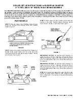
STEP 1: Remove mower from shipping carton. Mower
shown as removed from shipping carton with handles
folded in Figure 1.
FIGURE 1
STEP 2: Remove and discard cardboard from between all
handles. Raise upper handle until it is in line and seats
into lower handle. Securely tighten upper handle T-Knobs
on both sides. See Figure 2.
FIGURE 2
STEP 3: Raise upper and lower handle until it seats into
position in the lower handle brackets. Securely tighten
lower handle T-Knobs on both sides. See Figure 3.
FIGURE 3
IMPORTANT: DO NOT tip machine with carburetor or
spark plug down. Oil from crankcase will saturate the air
filter and cause the engine to be hard to start or not start
at all. If contamination does occur, the air filter will have to
be replaced.
IMPORTANT: DO NOT tip machine with carburetor or
spark plug down. Oil from crankcase will saturate the air
filter and cause the engine to be hard to start or not start
at all. If contamination does occur, the air filter will have to
be replaced.
STEP 4: Tip mower back against the upper handle to gain
access to cutting blade. Remove foam shipping block
from cutting blade. This must be removed before starting
the engine.
INSTRUCTION No. 7-3133 (REV 1, 2/12/01)
MOWER SHOWN AS REMOVED FROM SHIPPING
CARTON WITH HANDLES FOLDED (PUSH
MODEL SHOWN)
UPPER
HANDLE
UPPER
HANDLE
T-KNOB
LOWER
HANDLE
LOWER
HANDLE
T-KNOB
LOWER
HANDLE
BRACKET
UPPER HANDLE &
LOWER HANDLE
SHOWN IN POSITION
LOWER
HANDLE
T-KNOB


