background image

Summary of Contents for 6-3125

Page 1: ...Manual For 6 3125 CLAMSHELL GRASS CA TCHER KIT For 28 33 REAR ENGINE RIDING MOWERS 28 REAR ENGINE RIDER WITH CLAMSHELL BAGGER KIT SHOWN COPYRIGHT 2003 SNAPPER INC ALL RIGHTS RESERVED SNAPPER McDonough GA 30253 U S A MANUAL No 5 9260 I R 11 19 03 ...

Page 2: ... DO NOT operate machine on slopes exceeding 10 degrees 18 grade when equipped with grass catcher Exercise EXTREME CAUTION on all slopes Turn blades off when traveling uphill Use a slow speed and avoid sudden or sharp turns DO NOT operate machine across face of slopes Operate up and down Practice on slopes with blades off 11 12 13 AVOID uphill starts If machine stops going up hill or tires lose tra...

Page 3: ...e Pivot Bolt Installation 5 Hinge Adjustment Rear Cover 6 Front Weight Installation 6 7 Air Lift Kit 6 0480 Installation 7 Deck Adapter Installation 7 8 Grass Tube Installation 9 SECTION 2 OPERATION MAINTENANCE 10 Introduction 10 Grass Catcher Operation 10 Emptying Grass Catcher 10 If The Grass Catcher Becomes Clogged 10 Grass Catcher Maintenance 10 Before Each Use 10 Clamshell Assembly Components...

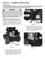
Page 4: ... with 2 piece type rear bumpers See Figure 1 1 will require replacement to complete installation Replace with one piece bumper PIN 3 6367 purchased separately from your local Snapper dealer The Bumper and Bumper Brackets will be attached to the Rider using bolts removed in the following steps RIGHT REAR BUMPER BOLTS_ FIGURE 1 2 B Remove top left bolt from bumper and the left frame bolt located at ...

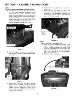
Page 5: ...ide cover Secure with 1 10 24 Flange Lock Nut Tighten securely HITCH PLATE FRONTCOVER FIGURE 1 4 B Place Front Cover Assembly over rear bumper and secure in place with spring loaded latch See Figure 1 5 1 2 NUT LOCK WASHER FIGURE 1 6 STEP 3 HINGE PIVOT BOLT INSTALLATION A Place Rear Cover Assembly on Front Cover Assembly aligning holes in hinge tabs Place one 3 8 flat washer between the two left H...

Page 6: ...tube C Insert stud into center hole of right Handle Link Add another 3 8 flat washer over stud and secure with hair pin See Figure 1 9 NOTE The right and left Handle Links contain 3 closely spaced holes to adjust the amount of force required to close and latch the Grass Catcher To increase the closing force and provide a tighter seal between the front and rear covers place stud in rear hole To dec...

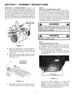
Page 7: ...vere injuries Wear heavy gloves when working on or handling blades DO NOT use blades that show signs of wear or damage FIGURE 1 11 A Attach 8 weight plates to the front frame of Rider using 2 3 8 16 x 3 hex head bolts and 4 heavy 3 8 flat washers Place one washer on each bolt B Align holes in weight plates with holes in frame Insert bolts through weight plates and frame See Figure 1 12 WARNING DO ...

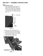
Page 8: ...the adapter lugs with the lug retainers in the hinge Push or lightly tap front of adapter towards the rear until tight against deck See Figure 1 15 DEFLECTOR REMOVED FLAT WASHER WING NUT FIGURE 1 16 E Attach tube latch to deck adapter Insert one 1 4 20 x 3 4 Carriage bolt from inside through lower hole in adapter Place Tube Latch over bolt followed by 1 4 Internal Tooth lock washer and secure with...

Page 9: ...ed by 1 4 Internal Tooth lock washers and secure with 2 1 4 20 hex nuts Tighten securely See Figure 1 18 HANDLE BASE TUBE HANDLE FIGURE 1 18 B Place deck in lowest cutting height setting C Slide upper end of Grass Tube end without Handle into opening in Front Cover Assembly D Slide lower end of Grass Tube over adapter and rotate towards mower to secure Handle Base under Latch See Figure 1 19 E Adj...

Page 10: ... maintain peak performance check the catcher screen located on the inside of the Rear Cover Assembly to make sure it is clean and free of any build up Clean as required with brush or broom F Close catcher Push down firmly on handle to ensure it is properly latched G Re start engine and drive machine to cutting area Set engine speed to highest setting engage blades and resume operation WARNING DO N...

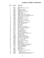
Page 11: ...CLAMSHELL ASSEMBLY COMPONENTS 17 _ 11 30 I 34 50 _ 37 27 40 33 6 48 29 30 49 31 _ 3 39 36 44 52 24 11 ...

Page 12: ... Hex Flange Lock 22 END CAP Tube WELDMENT Rear Cover Brace COVER Rear GRILL Rear Cover Not Shown BOLT 10 24 x 1 1 2 Oval Head 13 HINGE Rear Cover SCREW 10 24 x 1 1 2 Machine 5 DECAL Warning Not Shown LATCH Chute Tube BASE Handle HANDLE Tube BOLT 5 16 18 x 1 Carriage WASHER 1 4 Internal Tooth Lock 3 BOLT 1 4 20 x 3 4 Carriage 3 NUT 5 16 18 Wing NUT 1 4 20 Hex 3 PIN 3 8 Self Lock Cotter 2 WASHER 3 8...

Page 13: ...tallation Operator s Manual For 6 3125 CLAMSHELL GRASS CATCHER KIT For 28 33 REAR ENGINE RIDING MOWERS SNAPPER McDonough GA 30253 U S A COPYRIGHT 2003 SNAPPER PRODUCTS INC ALL RIGHTS RESERVED MANUAL No 5 9260 I R 11 19 03 13 ...

Reviews: