20
SECTION 6 – ADJUSTMENTS & REPAIRS
WARNING
DO NOT attempt any maintenance, adjustments or
service with the engine running. Stop engine. Stop
blades. Lock Traction Levers. Remove key.
Disconnect spark plug wires from spark plugs and
secure wires away from spark plugs. Engine and
components are HOT. Avoid serious burns, allow all
parts to cool before working on machine.
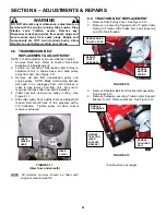
6.6.2. CUTTING DECK ADJUSTMENT
Cutting height can be adjusted by raising or lowering the
Cutting Deck, via Front Caster and Rear Axle
adjustments:
1. FRONT CASTER ADJUSTMENT: Each Caster Wheel
Assembly has five (5) 1/2” and two (2) 1/4” spacers
positioned on the caster shaft. By removing retainer pin,
and repositioning spacers above or below Caster
Support Tube, the spacers will raise or lower cutting
height in 1/2” increments. See Figure 6.8. NOTE: For
clearance purposes, one 1/4" spacer must remain below
caster support tube.
FIGURE 6.8
NOTE: Rear axle must be adjusted in conjunction with
front casters to achieve correct cutting height
adjustment.
2. REAR AXLE ADJUSTMENT: Position a floor jack
beneath rear of mower and raise mower. Loosen axle
bolts and adjust axle assembly up or down to
correspond with front caster adjustment. See Figure
6.9. NOTE: When adjusting axle make sure that rear of
cutting deck is 1/4" higher than front.
FIGURE 6.9
NOTE: Front casters must be adjusted in conjunction
with rear axle to achieve correct cutting height
adjustment.
NOTE: Traction rods may need to be adjusted after
cutting height adjustment is complete.
6.7 DECK BELT ADJUSTMENT &
REPLACEMENT
NOTE: For belt adjustment, proceed directly to step 5.
1.
Remove nut securing deck idler tensioning rod to
rod bracket, and slide rod out from bracket. See
Figure 6.10.
2.
Remove loosened belt from around blade spindle
pulleys, idler pulley and clutch pulley.
3.
Install new belt, using same pulley routing. See
Figure 6.10.
4.
Reinsert tensioning rod into rod bracket, and
secure with nut removed in previous step.
5.
Adjust belt tension by tightening or loosening
tensioning rod nut. Belt should have 10 lbs.
pressure with a 3/8” deflection.
FIGURE 6.10
SLIDE
CASTER
SHAFT
OUT
CASTER
SUPPORT TUBE
REMOVE
RETAINER PIN
NOTE: THOSE SPACERS
REMOVED FROM
BOTTOM OF CASTER
SHOULD BE
REINSTALLED AT TOP
BEFORE INSERTING
RETAINER PIN.
REPOSITION
SPACERS TO
ADJUST DECK
HEIGHT
LOOSEN
BOLTS
ADJUST
AXLE
TENSIONING
ROD NUT
CHECK
TENSION HERE
ROUTE AROUND
CLUTCH
Summary of Contents for SGV13321KW
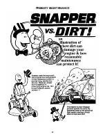
Page 27: ...27 PRIMARY MAINTENANCE...
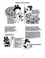
Page 28: ...28 PRIMARY MAINTENANCE...
Page 29: ...29 PRIMARY MAINTENANCE...
Page 30: ...30 PRIMARY MAINTENANCE...
Page 31: ...31 NOTES...


