

IQH3A IQ 3U Modular Enclosure
www.snellgroup.com
Installation
Issue 2 Rev 2
Page 20
©
2014 Snell Limited
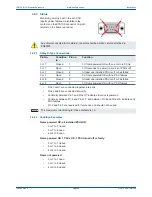
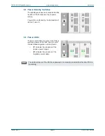
3.6.3 Status
3.6.3.1
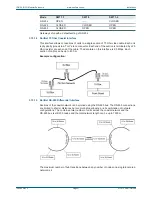
9-Way D-Type Connections
ghnghnW
•
Pins 3 and 7 are connected together internally
•
Pins 4 and 8 are connected internally
•
Continuity between Pin 1 and Pins 3/7 indicates the rack is powered
•
Continuity between Pin 6 and Pins 3/7, and between Pin 9 and Pins 4/8, indicates any
PSU failures
•
Pin 2 and Pin 5 are reserved for future use and should not be used
3.6.3.2
Condition Examples
Frame powered OK, all installed PSUs OK:
•
3 or 7 to 1 closed
•
3 or 7 to 6 open
•
4 or 9 to 9 open
Frame powered OK, 1 PSUs OK, 1 PSU turned off or faulty:
•
3 or 7 to 1 closed
•
3 or 7 to 6 closed
•
4 or 9 to 9 closed
Frame not powered:
•
3 or 7 to 1 open
•
3 or 7 to 6 closed
•
4 or 9 to 9 closed
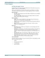
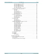
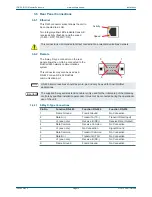
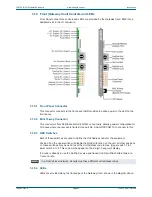
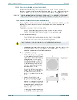
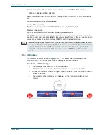
Monitoring circuitry built in to each PSU
reports power failures via isolated relay
contacts on the STATUS connector (9-pin D,
female) on the frame rear panel.
5
9
1
6
Any circuit connected to this status connector shall be a SELV circuit as defined in
EN60950.
Pin No.
Condition
to...
Pin no.
Function
3 or 7
Closed
1
3U frame powered OK with one or more PSUs
3 or 7
Open
1
3U frame has no power (no mains or PSUs off)
3 or 7
Closed
6
At least one installed PSU is off or has failed
3 or 7
Open
6
3U frame powered OK with no PSU failures
4 or 8
Closed
9
At least one installed PSU is off or has failed
4 or 8
Open
9
3U frame powered OK with no PSU failures
Note:
The maximum current rating for these contacts is 1 A.