

IQH3A IQ 3U Modular Enclosure
www.snellgroup.com
Operation
Issue 2 Rev 2
Page 42
©
2014 Snell Limited
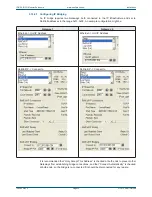
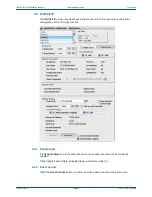
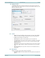
4.2.16.2
Pass WAN Packets
•
SP_IAM
: This controls whether the Gateway passes wide area I_AM packets from the
serial port to the RollCall Network. Normally this is enabled to allow PCs attached to
the serial port to be located by other units, but it may be disabled if you wish to control
the flow of I_AM packets through a system.
•
SP_TIME:
This controls whether the Gateway passes wide area TIME packets from
the serial port to the RollCall Network. Normally this is enabled to allow PCs attached
to the serial port to be time servers, but it may be disabled if you wish to control the
flow of TIME packets through a system.
4.2.16.3
Port Mode
This item shows the current operating mode of the serial port (RS-422, RS-232 or RS-485).
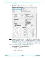
4.2.16.4
Report if PSUs Missing
When these boxes are checked it will allow a missing PSU report to be displayed in the Unit
Status area and logged.
If two power supply units are fitted, (dual redundancy supply configuration) the Left PSU and
the Right PSU items should be selected.
If for some reason one of the power supplies is removed a warning will be displayed,
indicating which power supply is missing.
If only one power supply is fitted, only the corresponding check box should be selected and
the other cleared.
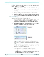
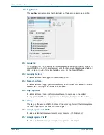
4.2.17 Long File packets
Check box to allow long file packet transfer on gateway. File packets changed between 227
bytes and 408. Leave disabled (short) unless advised by Snell engineering.
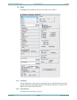
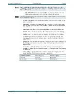
4.2.18 Fan Speed Override
This control only appears in IQH3A products where the backplane is of an old design. This
control is hidden for newer chassis types.
A temperature sensor is located at the rear fan. For older chassis that had the rear
temperature sensor connected through the module i2c bus, this control has been added to
allow user to override the fan speed. The default setting is Medium. For this chassis type, only
the inlet temperature is displayed. For all other chassis types, an automatic fan speed system
is used which increases fan speed for increases in temperatures or between inlet and outlet
temperatures.
Note:
Pass I_AM (Bridge) overrides both Pass I_AM (Serial) and Pass I_AM (IP). So if Pass
I_AM (Bridge) is set I AM messages will be passed over the bridge, irrespective of how the
other controls are set.
Note:
The Gateway will always use the received time stamp, whether it passes it on or not (but
see also Time from Logger).
Note:
If a PSU is fitted but fails or is turned off then a warning message will always be generated.


