background image

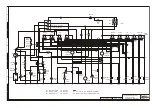
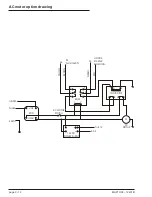
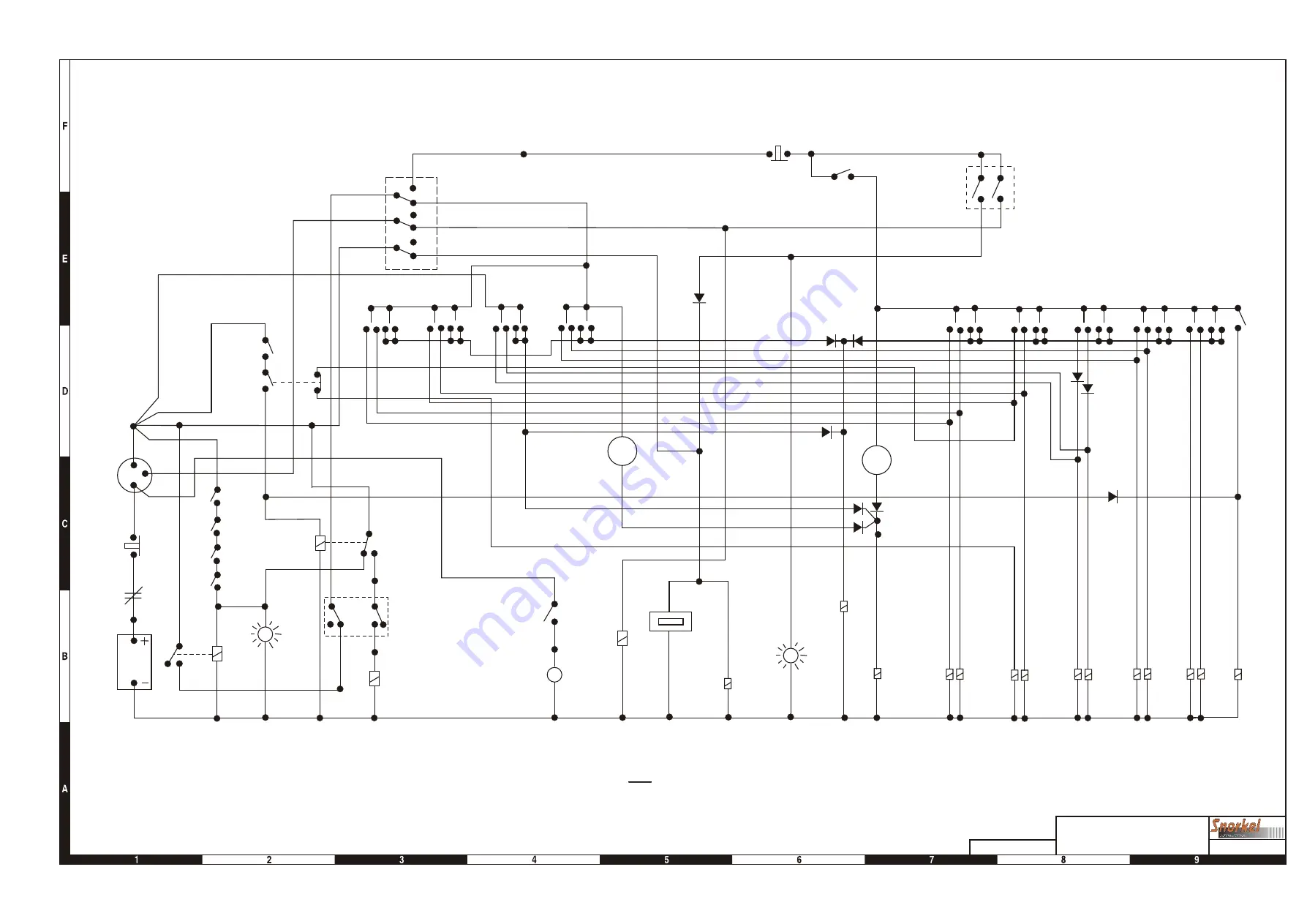
R1 = INTERLOCK RELAY
R2 = IGNITION RELAY
R3 = STABILISER RELAY

o

P/N  1650-010

o

P/N  1650-010

o

P/N  1650-010

Note:
(A1 - A12) and (B1 - B12) REPRESENT TERMINALS 
ON TERMINAL STRIP IN THE LOWER CONTROL BOX

TITLE

Electrical Schematic for
Lombardini diesel option
Snorkel model MHP13/35

B1

A5

EMERG

STOP

FOOT

SW

LOWER

BOOM

UPPER

BOOM

JIB

BOOM

SLEW

BLEED

DOWN

B11

SPEED

CONTROL

RHEOSTAT

SPEED

CONTROL

RHEOSTAT

PROPORTIONAL
COIL

CONTROL

COIL

DOWN

DOWN

UP

UP

EXT

RET

RIGHT

LEFT

BLEED

DOWN

LIFT

ENABLE

LIGHT

LIFT

ENABLE

LIGHT

A8

FUEL
SOLENOID

HOUR

METER

A4

A7

R3

R3

R2

R2

87A

87

A12

A11

A1

A3

STAB

COIL

START
SOLENOID

STAB/

BOOM

SW

A10

STAB

SW

A9

R1

85

30

87

87A

86

A2

IGN

START

BATT

EMERG

STOP

CIRCUIT

BREAKER

BATTERY

LOWER

BOOM

SWITCH

UPPER

BOOM

SWITCH

P

G

PLATFORM / GROUND

SELECTOR SWITCH.

LOWER

BOOM

UPPER

BOOM

JIB

BOOM

SLEW

A6

B12

85

85

86

86

30

B9

B8

B7

B6

B5

B4

B3

B2

LEFT

RIGHT

ROTATOR

OPTION

IGN

BATT

START

30

87

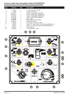
Electrical schematic, Lombardini diesel

Page 3-5

Summary of Contents for MHP1335

Page 1: ...Engine Powered Gasoline Diesel Battery Electric P N 12431B December 2005 V8 Maintenance and Repair Parts Manual ...

Page 2: ... upon which the part was installed THIS WARRANTY EXCLUDES AND SNORKEL DOES NOT WARRANT 1 Engines motors tires and batteries which are manufactured by suppliers to Snorkel who furnish their own warranty Snorkel will however to the extent permitted pass through any such warranty protection to the Customer or Dealer 2 Any Snorkel product which has been modified or altered outside Snorkel s factory wi...

Page 3: ...chedules vi Daily Maintenance vii Pre operational Inspection vii Hydraulic Hose Age vii 90 Day or 150 Hour Maintenance Trained Service Technician viii Yearly or 500 Hour Maintenance Trained Service Technician viii Lubricants ix Pressure gun application ix Rotation bearing ix Rotation gear teeth and pinion ix Engines ix Hydraulic oil reservoir ix Return filter x Battery x Preventive inspection main...

Page 4: ...embly drawing 1 6 Boom assembly 1 7 Jib boom assembly before SN NZ051005 1 8 Jib boom assembly drawing before SN NZ051005 1 9 Jib boom assembly drawing from SN NZ051005 1 10 Jib boom assembly from SN NZ051005 1 11 Column assembly before SN NZ050901 1 13 Column assembly drawing before SN NZ050901 1 15 Column assembly drawing after SN NZ050901 1 16 Column assembly after SN NZ050901 1 17 Column cover...

Page 5: ...basket outlet 4 16 240V AC basket outlet drawing 4 17 Ground power supply option drawing 4 18 Ground power supply option 4 19 Auto stabiliser option 4 20 Flashing light option 4 21 Section 3 Electrical Electrical schematic 3 3 Electrical schematic Auto stabiliser 3 4 Electrical schematic Lombardini diesel 3 5 Automatic stabiliser control box assembly before SN NZ051001 3 7 Automatic stabiliser con...

Page 6: ......

Page 7: ...orizontal reach 5 6m at 6m 19 8 at 19 8 Maximum wind speed 12 5m s 45kph 28mph Turntable rotation 540O non continuous or 360O continuous Power source std Gasoline engine 5 5hp Hydraulic system Proportional electro hydraulic Stabilisation 4 independently operated hydraulic outriggers with safety interlocks Stabiliser footprint max 3 7 x 3 6m 12 1 x 13 9 Standard colour Snorkel orange base and cover...

Page 8: ...9 9 cu in Bore x Stroke 68 x 45 mm 2 7 x 1 8 in Max output 4 kW 4 000 rpm Max torque 1 1 kg m 8 0 ft lb 2500 rpm Fuel gasoline Fuel Grade automotive gasoline unleaded or lowleaded preferred Fuel consumption 230 g PSh Cooling system Forced air Ignition system Transistor magneto PTO shaft rotation Counterclockwise Oil Capacity 0 60 litres 0 60 US qt 0 53 Imp qt Oil Grade SAE 10W 30 ...

Page 9: ... 12431B page iii General Specifications 13 12 11 10 9 8 7 6 5 4 3 2 1 METRES METRES 4 3 2 1 0 4 3 2 1 5 6 7 42 6 39 3 36 32 8 29 5 26 2 22 9 19 6 16 4 13 1 9 8 6 5 3 2 FEET FEET 13 1 9 8 6 5 3 2 0 3 2 6 5 9 8 13 1 16 4 19 6 22 9 ...

Page 10: ...page iv MHP13 35 12431B General Specifications 1 58m 53m 3 46m 5 99m 6 20m Includes optional rotator 51m 2 05m ...

Page 11: ... hydraulic schematics and individual components such as cylinders controls valves and solenoid operated valves Electrical Electrical Section 3 contains listings and drawings of electrical components installations including wiring schematics Options Options Section 4 contains parts listings and drawings of optional installations that may be installed on your unit Parts index Page locator The parts ...

Page 12: ...s New parts should remain in their container until they are ready to be used Clearly mark or tag hydraulic lines and electrical wiring connections when disconnecting or removing them from unit This will assure that they are correctly reinstalled Proper assembly is critical to the successful rebuilding of any unit Carefully inspect any parts which are to be reused If in doubt replace SAFETY FIRST i...

Page 13: ...ness Structural damage and welds Visually inspect weld cracks dents Lanyard anchor points Visually inspect condition Platform gate Visually inspect operation Platform guardrails Visually inspect condition Air filter Check condition Control switches Actuate and inspect operation Emergency lower Check operation causes correct motion Placards and decals Visually inspect installation condition Optiona...

Page 14: ...oco Super Sta 2 Above 32 Mobilgrease CM P Below 32 Mobilgrease CM L Platform rotator Check smooth operation Repair or replace if not working properly Platform controller Check smooth operation speeds Battery Check specific gravity 1 260 1 275 at 27 C Hydraulic return filter Check condition Replace if dirty Engine RPM Check for proper engine RPM 2500 See engine manufactures owner s manual Engine oi...

Page 15: ...r to the engine manufacturer s instruction manual or consult your local engine service representative if engine adjustments or repairs are needed The engine MUST be operated in accordance with manufacturer s instructions and serviced at recommended intervals Hydraulic oil reservoir Hydraulic oil reservoir The fluid level should be kept between the low and full marks on the sight gauge indicator an...

Page 16: ...of the boom The condition indicator is best observed from outside of the tract of the vehicle wheels to avoid a possible unsafe condition When changing the filter element the oil inside of the filter element should be examined for deposits of metal cuttings which if present could indicate excessive wear in some of the system components Battery Battery The battery will have longer life if the water...

Page 17: ... tubes 3 5 Decals and placards 2 8 Check OK X Platform rotator Optional 3 4 Platform rotation holding valve 3 4 Rotator mounting bolts 2 6 Platform Structural 1 Decals and placards 2 8 Platform gate 4 Hydraulic tubes and hoses 3 5 Platform mounting bolts 2 6 Correct operator s manual in document holder 2 Battery Battery terminals 6 7 Battery electrolyte level 5 Fuel Tank Fuel tank 3 5 Fuel tank ca...

Page 18: ...on Required Note If correction action is required on any item attach sheet indicating problem and action taken All items have been properly checked and tested and found to be operating satisfactory or necessary corrective action has been completed Inspected By Date ...

Page 19: ...0 106 950 118 750 220 235 430 475 165 175 320 355 93 250 99 200 145 550 161 550 300 320 580 650 225 240 435 485 M24 x 3 M24 x 2 M27 x 3 M27 x 2 353 384 459 496 154 100 167 600 200 350 216 500 740 805 1 080 1 170 555 605 810 875 209 700 228 100 272 650 294 600 1 010 1 100 1 470 1 590 755 820 1 100 1 150 M30 x 3 5 M30 x 3 M30 x 2 M33 x 3 5 M33 x 2 561 580 621 694 761 244 900 253 150 271 050 302 950 ...

Page 20: ...the responsibility of the user and their employer ANSI publications clearly identify the responsibilities of all personnel who may be involved with the aerial platform A reprint of the Manual of Responsibilities for Dealers Owners Users Operators Lessors and Lessees of ANSI SIA A92 5 1992 Boom Supported Elevating Work Platforms is available from Snorkel dealers or from the factory upon request Cop...

Page 21: ...d an equivalent force along the line of action of the manual force The calculated force due to wind is 248N or 25 3kg The load simulating the wind and manual force is therefore 70 1kg The test procedure is as follows Refer Figure 1 1 Set a pulley with rope 5 985m above the ground on a fixed pole 2 Place the machine so that the drawbar is pointing towards the fixed pole The centre of the slew beari...

Page 22: ...xvi MHP13 35 12431B Maintenance Information W ROPE o 63 3 7000 RATED LOAD R 239kg STANDARD MACHINE 217kg WITH ROTATOR 5985 7 5 0 2 R M W 70 1 CHAIN MANUAL FORCE M 44 8kg WIND FORCE W 25 3kg LOAD ON PULLEY 70 1kg o 0 5 ...

Page 23: ...lumn assembly drawing after SN NZ050901 1 16 Column assembly after SN NZ050901 1 17 Column covers 1 20 Column covers drawing 1 21 1500kg axle assembly drawing 1 22 1500kg axle assembly 1 23 Engine assembly before SN NZ050801 1 24 Engine assembly drawing before SN NZ050801 1 25 Engine assembly from SN NZ050801 1 26 Engine assembly drawing from SN NZ050801 1 27 Basket assembly 1 28 Basket assembly d...

Page 24: ...page 1 2 MHP13 35 12431B ...

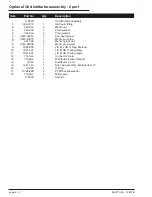
Page 25: ...24 9846 4 Foot plate weldment 25 9875 1 4 Reflector lens orange 26 9875 2 2 Reflector lens white 27 9948 4 Foot pin 28 9973 1 1 Safety chain 29 10993 1 1 Hammer lock 30 11112 3 1 Boom lock pin 31 11492 1 12 Tab washer 32 11572 1 Tow coupling 33 12467 2 Mudguard plastic 11585 2 Optional mudguard heavy duty steel 34 11585 3 2 Mud flap 12467 1 2 Plastic mud flap goes with plastic mud guard 36 12062 2...

Page 26: ...l and tyre assembly 12361 2 Wheel rim only 54 3603 20 1 Plain washer 55 3611 20 1 Nylock nut 56 3626 5 8 Flanged bush 57 3626 1 4 Flanged bush 58 12439 1 Hose protector 59 3603 12HD 4 Hardened washer 60 3604 06020 2 Screw page 1 4 MHP13 35 12431B Trailer assembly ...

Page 27: ...9 19 5 13 21 21 22 57 7 7 7 5 5 15 23 2 4 4 4 11 18 4 4 20 20 6 38 12 6 14 22 8 16 24 25 25 33 41 50 27 43 29 37 53 52 57 56 31 31 10 39 55 54 51 47 49 26 34 60 42 28 36 44 30 46 32 40 48 X3 X3 X3 X3 23 45 45 57 57 57 Revision A 3 May 2005 Trailer assembly drawing Page 1 5 ...

Page 28: ...orkel Model MHP13 35 DWG 12390 9 3 1 2 31 17 40 4 38 32 35 36 37 11 19 27 25 5 13 21 7 15 23 10 12 20 14 22 8 16 24 25 33 11 11 11 11 39 6 27 11 11 29 26 34 11 11 7 7 10 10 10 10 10 28 28 30 X9 Boom assembly drawing Page 1 6 ...

Page 29: ...rest 19 12373 1 Floating turret weldment 20 12374 1 Upper level rod 21 12375 2 Lower level rod 22 12380 1 Pin 23 12383 1 Quadrant jib upper boom weldment 24 12393 1 Pin 25 12394 2 Pin 26 12395 1 Pin 27 12396 2 Pin 28 12397 2 Pin 29 12432 2510 2 Nylon spacer washer 30 12432 3010 4 Nylon spacer washer 31 12445 1 Micro switch 32 12062 2 Pin lock retainer 33 12333A 1 Upper lift cylinder 34 12334A 1 Lo...

Page 30: ... 100 1 Upper flyboom weldment 8 12288 110 1 Lower flyboom weldment 9 12347 5 Pin 20 x 134mm 10 12380 1 Pin 25 x 115 11 12383 1 Quadrant jib upper boom weldment 12 12327A 1 Basket assembly 13 12332A 1 Flyboom cylinder 14 3611 10 6 Nylock nut 15 12451 3 As Req Basket spacer 16 3610 10050 4 Bolt 17 3610 10070 2 Bolt 18 3603 10 12 Washer plated 19 12451 1 Fixed basket mounting page 1 8 MHP13 35 12431B...

Page 31: ...E Jib Boom Assembly Snorkel Model MHP13 35 DWG 12390 Jib 1 9 9 9 9 9 3 3 3 3 3 3 3 3 3 3 11 5 13 7 2 2 10 4 4 12 6 8 15 X6 x4 17 19 18 18 18 18 14 14 16 Jib boom assembly drawing before SN NZ051005 Page 1 9 ...

Page 32: ...TLE Jib Boom Assembly Snorkel Model MHP13 35 DWG 12390 Jib 1 9 9 9 9 9 3 3 3 3 3 3 3 3 3 3 11 5 13 7 2 2 10 4 4 12 6 8 15 X6 17 19 18 18 18 18 14 14 16 Jib boom assembly drawing from SN NZ051005 Page 1 10 ...

Page 33: ...120 1 Upper flyboom weldment 8 12288 110 1 Lower flyboom weldment 9 12347 5 Pin 20 x 134mm 10 12380 1 Pin 25 x 115 11 12383 1 Quadrant jib upper boom weldment 12 12327A 1 Basket assembly 13 12332A 1 Flyboom cylinder 14 3611 10 6 Nylock nut 15 12451 3 As Req Basket spacer 16 3610 10050 4 Bolt 17 3610 10070 2 Bolt 18 3603 10 12 Washer plated 19 12451 1 Fixed basket mounting MHP13 35 12431B page 1 11...

Page 34: ......

Page 35: ... Nyloc nut 26 12483 1 Remote grease nipple mount 27 3611 12 2 Nyloc nut 28 3613 12035 10 Cap screw 29 3631 12 10 Disc lock washer 30 3631 16 12 Disc lock washer 31 3660 05020 8 Counter sunk screw 32 8628 1 Pin keeper 33 12453 2 Lock tab 34 10268 2 1 Battery bracket 35 12445 90DEG 1 Micro switch 36 11406 1 Lower control box 37 11492 1 1 Tab washer 38 11943 1 Slew drive and brake assembly 39 12239 3...

Page 36: ...Item Part No Qty Description 56 12483 4 1 Tube 57 12483 3 1 Connector 58 12483 2 1 Adaptor page 1 14 MHP13 35 12431B Column assembly before SN NZ050901 ...

Page 37: ...37 45 31 39 5 53 47 33 18 34 42 36 44 26 54 38 52 46 32 40 49 50 15 8 35 TITLE 1 21 23 2 29 28 30 7 20 14 16 48 MAIN CONTROL MANIFOLD See Hydraulics Section ENGINE ASSEMBLY See Repair Parts Section HYDRAULIC OIL TANK ASSEMBLY See Hydraulics Section 55 58 57 56 Revision A June 15 2005 Column assembly drawing before SN NZ050901 Page 1 15 ...

Page 38: ... 43 37 45 31 39 5 53 47 33 18 34 42 36 44 26 54 38 52 46 32 40 49 50 15 8 35 TITLE 1 21 23 2 29 28 30 7 20 14 16 48 MAIN CONTROL MANIFOLD See Hydraulics Section ENGINE ASSEMBLY See Repair Parts Section HYDRAULIC OIL TANK ASSEMBLY See Hydraulics Section 55 58 57 56 59 14 7 19 60 60 Column assembly drawing after SN NZ050901 Page 1 16 ...

Page 39: ... Nyloc nut 26 12483 1 Remote grease nipple mount 27 3611 12 2 Nyloc nut 28 3613 12035 10 Cap screw 29 3631 12 10 Disc lock washer 30 3631 16 12 Disc lock washer 31 3660 05020 8 Counter sunk screw 32 8628 1 Pin keeper 33 12453 2 Lock tab 34 10268 2 1 Battery bracket 35 12445 90DEG 1 Micro switch 36 12521 1 Lower control box 37 11492 1 1 Tab washer 38 11943 1 Slew drive and brake assembly 39 12239 3...

Page 40: ...tem Part No Qty Description 56 12483 4 1 Tube 57 12483 3 1 Connector 58 12483 2 1 Adaptor 59 12381 40 1 Heat deflector 60 9990 4 Thrust washer page 1 18 MHP13 35 12431B Column assembly after SN NZ050901 ...

Page 41: ......

Page 42: ...6 1 Spur washer 7 3660 05020 20 Countersunk screw 8 12388 1 1 Cover engine side 9 12388 2 1 Cover hydraulic tank side 10 12388 3 1 Cover door 11 12388 4 1 Cover rear 12 12401 1 Latch compression 13 12403 2 Butt hinge 14 12414 20 2 Stay pivot mount 15 12414 5 2 Cover stay weldment 16 12440 2 Tool clip 17 60038 006 2 Split pin 18 5510014 2 Latch side cover page 1 20 MHP13 35 12431B Column covers ...

Page 43: ...TITLE Covers Snorkel Model MHP13 35 DWG 12381A 1 1 7 7 7 13 9 15 11 17 5 5 2 8 14 3 16 4 10 18 6 12 Column covers drawing Page 1 21 ...

Page 44: ...3 4 6 6 6 25 20 A 900 NOMINAL SLOT CENTRES 1400 WHEEL MOUNT FACES 8 15 24 15 14 19 21 15 22 23 TITLE 1500kg Axle Assembly Hydraulic disc brakes Snorkel Model MHP13 35 DWG A11570 Rev A 14 3 2005 1500kg axle assembly drawing Page 1 22 ...

Page 45: ...es 10 11 10 Ref Washer 11 Ref Split pin 12 9922 7 2 Grease cap 13 2045 001 Ref Caliper assembly Includes items 14 to 24 14 9945 9 2 Anchor plate 15 2045K Ref Seal kit caliper 17 2045 003 2 Bleed screw 18 2045 13 2 Housing 19 2045 5 4 Guide pin 20 3605 08 4 Spring washer M8 21 3610 08030 4 Set screw M8 x 30 HT 22 60005 013 2 Lockwasher 23 3610 12035 2 Set screw M12 x 35 HT 24 2045 010 2 Piston 25 1...

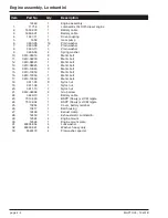
Page 46: ...tric bolt 20 3610 10065 3 Metric bolt 21 3611 04 2 Metric nylock nut 22 3611 06 1 Metric nylock nut 23 3611 08 4 Metric nylock nut 24 3611 10 11 Metric nylock nut 25 3612 06006 2 Metric grub screw 26 3649 10 1 Battery cable 27 7013 003 1 BSPP Dowty x JICM nipple 28 7013 004 1 BSPP Dowty x JICM nipple 29 8398 1 Spring 30 8978 1 2 Screw self tapping 31 10254 1 Cover battery terminal 32 10350 4 1 Exh...

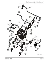
Page 47: ...ngine assembly drawing before SN NZ050801 1 9 17 3 11 19 5 13 21 7 15 23 2 10 10 10 10 43 18 4 12 20 6 22 8 16 24 25 33 27 29 37 31 39 26 35 34 28 36 30 38 32 40 42 41 DWG 12413 24 24 24 Engine assembly drawing before SN NZ050801 ...

Page 48: ...20 3610 10055 1 Metric bolt 21 3610 10065 3 Metric bolt 22 3611 04 2 Metric nylock nut 23 3611 05 8 Metric nylock nut 24 3611 06 2 Metric nylock nut 25 3611 08 4 Metric nylock nut 26 3611 10 4 Metric nylock nut 27 3612 06006 2 Grub screw 28 3649 10 1 Battery cable 29 7013 003 1 BSPP Dowty x JICM nipple 30 7013 004 1 BSPP Dowty x JICM nipple 31 8398 1 Spring 32 8978 1 2 Screw self tapping 33 10254 ...

Page 49: ...Engine assembly drawing from SN NZ050801 DWG 12413 1 9 9 17 3 11 11 19 5 13 21 7 15 23 2 10 10 18 4 12 20 6 14 22 8 16 24 25 33 41 27 35 43 29 37 45 31 39 26 26 34 42 28 36 44 30 38 32 40 Engine assembly drawing from SN NZ050801 ...

Page 50: ... Nylock nut 19 3611 08 6 Nylock nut 20 3668 06020 6 Cap screw 21 7895 4 Anti rattle button 22 12327 1 Basket weld 23 12327 1 1 Floor plate 24 12327 32 2 Light guard 25 12327 50 1 Gravity gate 26 12327 55 2 Cable protector 27 12327 53 2 Roller 28 12386 1 2 Tail lamp LED 12473 2 Tail lamp SAE LED combination US approved 29 12386 2 2 Licence plate lamp LED 30 12386 3 2 Red reflector 31 1815 1 Nylon c...

Page 51: ...MHP13 35 12431B page 1 29 Basket assembly drawing 1 8 4 12 29 30 28 11 21 7 2 10 18 5 4 13 12 20 8 3 9 31 17 24 14 26 23 22 16 6 27 6 5 18 19 25 15 DWG 12327A Basket assembly drawing ...

Page 52: ... 1 Lock pin spring Includes 11 11 1 Lock pin 12 9946 10 1 Adjusting screw M16 13 9946 8 1 Handle assembly Including 14 15 16 17 14 1 Tension pin 15 1 Tension pin 16 9946 9 1 Trigger assembly Including 15 16 17 17 1 Trigger spring 20 10053 4 1 Master cylinder 21 10053 1 1 Plastic cap Includes 22 23 22 1 Deflector 23 1 Gasket 26 10053 7 1 Rubber boot 27 11572 3 1 Pushrod 29 11572 4 1 Bracket handle ...

Page 53: ...MHP13 35 12431B page 1 31 Tow coupling hydraulic drawing H Y D R A D I S C 12 16 29 17 2 22 21 30 32 23 26 27 31 5 4 3 1 6 8 7 20 13 14 15 9 10 11 DWG 11572 Tow coupling hydraulic drawing ...

Page 54: ...ger explosive gas 18 11420 1 Decal lower control box 19 0323899 2 Decal electrocution hazard 20 0150602 4 Decal descending boom 21 451986 6 Decal limit switches 22 9223 3 8 Decal chevron 23 12448 1 Decal outrigger control 24 8945 1 Decal vin plate 25 7856 45 2 Decal tyre pressure 26 12423 250 1 Decal safe working load NZ Aust machines without rotator 12423 227 1 Decal safe working load NZ Aust mac...

Page 55: ...13 35 12431B page 1 33 Placards and decals drawing 7 4 2 19 12 15 15 1 31 28 9 13 17 21 25 29 18 23 12 14 20 24 25 19 20 20 20 6 9 22 x 8 28 21 x 4 11 x 4 16 19 10 30 3 26 8 27 Placards and decals drawing ...

Page 56: ......

Page 57: ...ft cylinder assembly 2 5 Lower lift cylinder assembly 2 6 Flyboom cylinder assembly 2 7 Stabiliser leg cylinder assembly 2 8 Hydraulic oil tank assembly 2 9 Optional Rotator cylinder assembly 2 10 Optional Oil distributor assembly 2 port 2 11 Optional Oil distributor assembly drawing 2 12 Optional Automatic stabiliser 2 13 MHP13 35 12431B page 2 1 Section 2 Hydraulics ...

Page 58: ...page 2 2 MHP13 35 12431B ...

Page 59: ...ALVE ACCUM S S ORIFICE FLOW CONTROL VALVE STABILISER PORT PROPORTIONAL FLOW CONTROL VALVE RETURN FILTER 10 MICRON ROTATOR OPTION T P PILOT OPER CHECK VALVE AUX MOTOR OPTION PUMP HONDA PUMP AUX MOTOR LEG 4 P LEG CYL 2500 psi JIB CYL T TITLE Hydraulic schematic for standard machines Snorkel model MHP13 35 DWG 0000000 X Hydraulic schematic drawing for standard units Page 2 3 ...

Page 60: ... MAIN VALVE EMERGENCY LOWER PORT CONTROL VALVE TANK PORT TANK PORT 2500 p s i RELIEF VALVE ACCUM S S ORIFICE FLOW CONTROL VALVE STABILISER PORT PROPORTIONAL FLOW CONTROL VALVE RETURN FILTER 10 MICRON ROTATOR OPTION T P PILOT OPER CHECK VALVE AUX MOTOR OPTION P PUMP HONDA PUMP AUX MOTOR LEG 4 LEG CYL JIB CYL T X Hydraulic schematic drawing for units fitted with self level stabilisers Page 2 4 ...

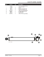
Page 61: ...ower 6 11415 6 1 Check valve 4 psi 7 11415 7 1 Proportional flow control 8 11415 8 1 Control solenoid 9 11415 9 1 Solenoid valve closed centre 10 11415 10 4 Solenoid valve floating centre 11 11415 6 1 Check valve 4 psi 12 11415 11 12 Solenoid coil 12 volt 13 11415 12 1 Minimum flow setting orifice 14 11415 12 1 Emergency lowering orifice 15 10996 1 1 Test point MHP13 35 12431B page 2 4 Main contro...

Page 62: ...ft cylinder 12333K 1 Seal kit 2 3626 6 4 Flanged permaglide bush 3 7031 002 1 JICM x UN O Ring M elbow 4 10856 1 1 Counterballance cartridge 5 10856 2 1 Check cartridge 6 10856 3 1 Velocity fuse 7 506 5705 2 JICM x UN O Ring M nipple page 2 5 MHP13 35 12431B Upper lift cylinder assembly 1 3 5 7 2 2 4 6 DWG 12333A ...

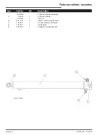
Page 63: ...K 1 Seal kit 2 3626 1 2 Flanged permaglide bush 3 3626 6 2 Flanged permaglide bush 4 7031 002 1 JICM x UN O Ring M Elbow 5 10856 1 1 Counterbalance cartridge 6 10586 2 1 Check cartridge 7 10586 3 1 Velocity fuse 8 506 5705 2 JICM x UN O Ring M Nipple MHP13 35 12431B page 2 6 Lower lift cylinder assembly 1 3 5 8 7 2 4 6 DWG 12334A ...

Page 64: ... cylinder assembly 1 12332 1 Flyboom cylinder 12332K 1 Seal kit 2 7031 002 2 JICM x UN O Ring M elbow 3 10856 1 1 Counterbalance cartridge 4 10976 1 1 Cavity plug 5 3626 10 4 Flanged permaglide bush page 2 7 MHP13 35 12431B Flyboom cylinder assembly 1 3 2 4 4 DWG 12332A ...

Page 65: ... 04 2 Metric Nylock nut 9 3626 1 4 Flanged permaglide bush 10 10286 3 1 Counterbalance cartridge 11 10286 4 1 Check cartridge 12 12336 10 1 Limit switch 13 12336 11 1 Sliding bush 14 12336 2 1 Cylinder base 15 12336 3 1 Wiper seal 16 12336 4 1 Switch mount 17 12336 7 1 Rubber spring 18 12425 1 Leg cylinder guard 19 7031 002 2 JICM x UN O Ring M elbow 20 3603 04 2 Plain washer MHP13 35 12431B page ...

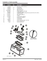
Page 66: ... 11 11430 7 1 Suction pipe weldment 12 11487 1 Filter breather 13 11488 10 1 Tank top filter 14 302950 1 Decal hydraulic oil level min max 15 451776 1 Decal hydraulic fluid 16 9207 1 Decal hydraulic oil page 2 9 MHP13 35 12431B Hydraulic oil tank assembly 175mm F U L L A D D 302 950 HYDRAULIC OIL 451 776 H Y D R A U L IC F L U ID L E V E L C H E C K FL U ID LE V E L W IT H P LA TF O R M LO W E R E...

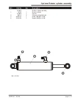
Page 67: ...on 12330A Rotator cylinder assembly 1 12330 1 Rotator cylinder 12330K 1 Seal kit 2 3626 3 2 Flanged permaglide bush 3 7046 012 1 Elbow BSPTM x JICM 4 7019 018 1 Nipple BSPTM x JICM MHP13 35 12431B page 2 10 Optional Rotator cylinder assembly 4 1 3 2 2 DWG 12330A ...

Page 68: ...5 3 Metric nylock nut 8 3612 05008 1 Metric grub screw 9 7025 002 1 JIC M x UN O Ring M elbow 10 7031 001 1 JIC M UN O Ring elbow 11 7031 007 1 JIC M UN O Ring nipple 12 11413 6 1 Connector male 13 11956 4 1 Distributor rotation bracket 14 11957 1 Distributor 2 port 15 12411 10 1 Slip ring assembly includes item 12 16 13 228 3 O Ring 17 11768 228 2 PTFE backup washer 18 11956 5 2 Wiper seal 11957K...

Page 69: ...MHP13 35 12431B page 2 12 Optional Oil distributor assembly drawing Op tio na l Oil di str ib ut or as se m bl y dr aw in g 1 9 17 17 3 11 5 13 7 15 2 10 18 18 4 12 6 14 8 16 16 16 DWG 12443 ...

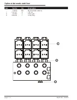
Page 70: ...omatic stabiliser Item Part No Qty Description 11921A Ref Manifold block assembly 1 11415 11 8 12V coil 2 11415 9 4 Valve spool 3 7034 001 1 Cavity Plug page 2 13 MHP13 35 12431B Optional Automatic stabiliser 1 3 2 ...

Page 71: ...x assembly before SN NZ051001 3 7 Automatic stabiliser control box assembly after SN NZ051001 3 8 Upper control box assembly 3 9 Lower control box assembly before SN NZ050901 3 10 Lower control box assembly from SN NZ050901 3 11 AC motor option drawing 3 12 AC motor option with 240VAC outlet drawing 3 13 MHP13 35 12431B page 3 1 Section 3 Electrical ...

Page 72: ......

Page 73: ...AT SPEED CONTROL RHEOSTAT PROPORTIONAL COIL CONTROL COIL DOWN DOWN UP UP EXT RET RIGHT LEFT BLEED DOWN LIFT ENABLE LIGHT LIFT ENABLE LIGHT A8 HONDA STARTER HOUR METER R2 R2 87A 30 85 86 CHOKE SOLENOID HONDA COIL A4 CHOKE B10 A7 R3 R3 87A 87 A12 A11 A3 STAB COIL STAB BOOM SW A10 STAB SW A9 R1 85 30 87 87A 86 A2 IGN START BATT EMERG STOP CIRCUIT BREAKER BATTERY LOWER BOOM SWITCH UPPER BOOM SWITCH P ...

Page 74: ...Page 3 4 Electrical schematic Auto stabiliser ...

Page 75: ...D CONTROL RHEOSTAT PROPORTIONAL COIL CONTROL COIL DOWN DOWN UP UP EXT RET RIGHT LEFT BLEED DOWN LIFT ENABLE LIGHT LIFT ENABLE LIGHT A8 FUEL SOLENOID HOUR METER A4 A7 R3 R3 R2 R2 87A 87 A12 A11 A1 A3 STAB COIL START SOLENOID STAB BOOM SW A10 STAB SW A9 R1 85 30 87 87A 86 A2 IGN START BATT EMERG STOP CIRCUIT BREAKER BATTERY LOWER BOOM SWITCH UPPER BOOM SWITCH P G PLATFORM GROUND SELECTOR SWITCH LOWE...

Page 76: ......

Page 77: ... 4 LED 12V green from Serial number NZ050901 3 3604 05020 2 Pan head screw 4 302 0016 5 Switch toggle SPDT M OFF M 5 3020097 1 Switch toggle DPDT 6 304 0411 1 Audible alarm not shown 7 12416 1 Hinge not shown 8 1650 010 1 Relay not shown 9 304 0338 1 Plug assembly not shown 10 12408 1 Seal not shown 11 7084 005 6 Seal MHP13 35 12431B page 3 7 Automatic stabiliser control box assembly before SN NZ0...

Page 78: ...04 1 Control box 2 12536 3 5 LED 12V green from Serial number NZ050901 3 3604 05020 2 Pan head screw 4 302 0016 5 Switch toggle SPDT M OFF M 5 12416 1 Hinge not shown 6 12408 1 Seal not shown 7 12515 5 Washer 8 1815 2 Cable gland not shown page 3 8 MHP13 35 12431B Automatic stabiliser control box assembly after SN NZ051001 1 3 5 2 2 4 7 7 ...

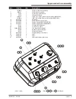
Page 79: ... 1 Knob speed control switch 7 302 0018 4 Switch toggle DPDT M OFF M 8 302 0015 2 Switch toggle SPST MOM OFF 9 10114 1 Contact set additional 10 12385 1 Control box upper 11 3604 05020 2 Pan head screw plated 12 12408 1 Rubber seal not shown 13 12416 1 Hinge not shown 14 304 0338 1 Plug assembly not shown 15 7084 005 6 Seal 16 7084 007 1 Seal 17 302 0018 1 Used with rotate option only MHP13 35 124...

Page 80: ... 7 3020087 1 Key switch 8 304 0348 1 Knob speed control switch 9 304 0412 1 Rheostat 25 ohm 10 455186 1 Hourmeter 12 60VDC square 11 560377 1 Lamp 12V green before serial number NZ051001 12521A 1 LED 12V green from serial number NZ051001 12 56223 6 1 Switch guard 13 56368 6 1 Circuit breaker 15 amp page 3 10 MHP13 35 12431B Lower control box assembly before SN NZ050901 LOWER BOOMS STABILISER BASE ...

Page 81: ... 455186 1 Hourmeter 9 560377 1 Lamp 12V green before serial number NZ051001 12521A 1 LED 12V green after serial number NZ051001 10 3020087 1 Key switch 11 304 0412 1 Rheostat 12 9776 2 Collar and contact block 13 302 0018 4 Switch toggle DPDT M OFF M 14 302 0015 1 Switch toggle SPST MOM OFF 15 302 0048 1 Switch toggle 4PDT ON ON 16 302 0097 1 Switch toggle DPDT ON ON MHP13 35 12431B page 3 11 Lowe...

Page 82: ...ion drawing HONDA STARTER SOLENOID AC MOTOR SWITCH A4 R2 terminal 85 YELLOW BROWN GREEN RED A5 RELAY 4 1 3 5 8 6 7 2 CONTACTOR 0 1 2 4 6 8 M AC MOTOR PHASE NEUTRAL EARTH POWER SUPPLY 12v DC To B12 To A8 LINE RCD LOAD AC motor option drawing ...

Page 83: ...g HONDA STARTER SOLENOID SOCKET OUTLET AC MOTOR SWITCH A4 R2 terminal 85 YELLOW BROWN GREEN RED A5 RELAY 4 1 3 5 8 6 7 2 CONTACTOR 0 1 2 4 6 8 M AC MOTOR PHASE NEUTRAL EARTH POWER SUPPLY 12v DC To B12 To A8 P N E LINE RCD LOAD AC motor option with 240VAC outlet drawing ...

Page 84: ......

Page 85: ...drawing 4 8 Step assembly 4 9 Honda 240V gas AC option 4 10 Honda 240V gas AC option drawing 4 11 Electric motor supply box 4 13 240 AC motor 4 14 Continuous rotation option 4 15 240V AC basket outlet 4 16 240V AC basket outlet drawing 4 17 Ground power supply option drawing 4 18 Ground power supply option 4 19 Auto stabiliser option 4 20 Flashing light option 4 21 MHP13 35 12431B page 4 1 Section...

Page 86: ... 08045 4 Metric bolt 20 3610 10055 1 Metric bolt 21 3610 10065 3 Metric bolt 22 3611 04 2 Metric nylock nut 23 3611 05 8 Metric nylock nut 24 3611 06 2 Metric nylock nut 25 3611 08 4 Metric nylock nut 26 3611 10 4 Metric nylock nut 27 3612 06006 2 Grub screw 28 3649 10 1 Battery cable 29 7013 003 1 BSPP Dowty x JICM nipple 30 7013 004 1 BSPP Dowty x JICM nipple 31 8398 1 Spring 32 8978 1 2 Screw s...

Page 87: ...e 4 3 Engine assembly Robin drawing DWG 12450 1 9 9 17 11 19 5 13 21 7 23 2 10 10 18 4 12 20 6 14 22 8 3 16 13 13 16 24 25 33 41 27 35 43 29 37 45 31 39 26 34 42 28 36 44 30 38 32 40 11 15 26 Engine assembly Robin drawing ...

Page 88: ... bolt 14 3610 10045 3 Metric bolt 15 3610 10050 1 Metric bolt 16 3610 10055 1 Metric bolt 17 3610 10060 3 Metric bolt 18 3611 05 8 Nyloc nut 19 3611 08 1 Nyloc nut 20 3611 10 7 Nyloc nut 21 3612 06006 2 Grub screw 22 3649 10 1 Battery cable 23 7013 003 1 BSPP Dowty x JICM nipple 24 7013 004 1 BSPP Dowty x JICM nipple 25 10254 1 Cover battery terminal 26 10417 1 Bell housing 27 12409 1 Exaust clamp...

Page 89: ...MHP13 35 12431B page 4 5 Engine assembly Lombardini drawing 1 9 17 17 17 3 11 19 5 13 21 7 15 23 2 10 20 18 4 12 20 6 14 22 8 16 24 25 33 27 29 31 26 28 30 32 x3 Engine assembly Lombardini drawing ...

Page 90: ... 2 Pin 20 x 134mm 10 3610 10070 2 Bolt 11 3611 06 2 Nylock nut 12 12327A 1 Basket assembly 13 3603 06 4 Plain washer 14 3613 06080 2 Cap screw 15 506 5705 4 JIC M x UN O Ring Nipple 16 11586 1 Double pilot check valve 17 12468 16 1 Valve mount 18 3626 5 2 Flanged bush 19 12330A 1 Rotator cylinder 20 3626 3 2 Flanged bush 21 12468 22 1 Pin 22 8628 4 Pin keeper 23 11492 1 4 Tab washer 24 3610 06012 ...

Page 91: ...TITLE Basket Rotator Assembly Snorkel Model MHP13 35 DWG 12468 9 9 3 3 25 26 25 12 1 21 22 24 23 17 11 19 5 13 7 15 2 10 18 20 6 14 8 16 4 4 Revision A 3 May 2005 Basket rotator drawing Page 4 7 ...

Page 92: ...TITLE Fold Down Step Assembly Snorkel Model MHP13 35 DWG 000000 1 1 1 9 9 3 3 11 5 7 2 2 10 4 4 12 6 6 8 8 8 8 Basket Assembly ATTACHMENT DETAIL 13 15 14 x8 x4 x4 Step assembly drawing Page 4 8 ...

Page 93: ...668 08025 2 Socket button head screw 7 11429 32 2 Bush 8 11429 33 4 Spring retainer 9 11429 34 2 Spring 10 12480 10 1 Step mount left 11 12480 20 1 Step mount right 12 12480 30 1 Rung weldment all machines before Serial Number NZ050701 12480 300 1 Rung weldment all machines from Serial Number NZ050701 13 3611 10 4 Nylock nut 14 3603 10 8 Plain washer 15 3610 10070 4 Bolt MHP13 35 12431B page 4 9 S...

Page 94: ... 10 12 Plain washer 6 3610 10045 4 Bolt 7 3611 10 8 Nylock nut 8 9018 5 1 240V AC motor assembly 9 3610 10055 1 Bolt 10 3610 10065 3 Bolt 11 5560179 4 Plain washer 12 12413A 1 Honda engine assembly 13 3603 05 4 Plain washer 14 3611 05 4 Nylock nut 15 3604 05020 4 Bolt 16 12486A 1 Electric motor supply box page 4 10 MHP13 35 12431B Honda 240V gas AC option ...

Page 95: ... 5 5 5 13 7 7 15 2 10 4 12 6 14 8 16 POWER SUPPLY UNIT 240V AC MOTOR ASSEMBLY See Options Section MOTOR ASSEMBLY See Repair Parts Section TRAILER ASSEMBLY See Repair Parts Section ELECTRIC MOTOR SUPPLY BOX See Options Section Honda 240V gas AC option drawing Page 4 11 ...

Page 96: ......

Page 97: ...ply box 2 1815 1 Compression gland 3 1865 001 1 Switch 4 2500 5 1 Relay 5 2500 6 1 Relay mounting base 6 10967 1 1 RCD 7 10967 2 1 Appliance inlet 8 10967 4 1 Enclosure lid 9 10967 6 1 Enclosure 10 11588 1 Relay MHP13 35 12431B page 4 13 Electric motor supply box 1 9 3 5 7 2 10 4 6 8 ...

Page 98: ... 8 3610 06025 4 Bolt 9 6983 001 1 JIC F tapped hole plug 10 7013 003 1 BSPP x JICM nipple 11 9501 2 1 Hydraulic fitting 12 11058 1 1 Check fitting 13 3605 10 4 Plain washer 14 3611 10 4 Nylock nut 15 1867 005 2 Motor foot plate 16 3610 08035 4 Bolt 17 3605 08 4 Spring washer 18 3603 08 4 Plain washer 19 361070045 4 Bolt 20 3603 10 4 Plain washer page 4 14 MHP13 35 12431B 240 AC motor 1 9 17 3 11 1...

Page 99: ...asher 4 12452 1 Distributor drive 5 11957A 1 Oil distributor 6 3603 06 4 Plain washer 7 3605 06 4 Spring washer 8 3610 06020 4 Bolt MHP13 35 12431B page 4 15 Continuous rotation option OIL DISTRIBUTOR See Hydraulics Section COLUMN ASSEMBLY See Repair Parts Section TRAILER ASSEMBLY See Repair Parts Section 1 3 5 7 2 4 6 8 ...

Page 100: ...40V AC basket outlet 2 1807 1 Appliance outlet 3 1865 001 1 Switch 4 10263 1 Compression gland 5 10967 3 1 Switch enclosure 6 10967 5 4 Mounting feet 7 3611 05 4 Nylock nut 8 3603 05 8 Plain washer 9 3610 05010 4 Bolt page 4 16 MHP13 35 12431B 240V AC basket outlet ...

Page 101: ...Basket Assembly ATTACHMENT POSITION ATTACHMENT DETAIL 9 9 7 7 240V AC BASKET OUTLET 1 3 5 2 4 6 8 8 TITLE 240V AC Basket Outlet Snorkel Model MHP13 35 DWG 240V AC basket outlet drawing Page 4 17 ...

Page 102: ...TITLE Ground Power Supply Snorkel Model MHP13 35 DWG ATTACHMENT POSITION GROUND POWER SUPPLY ATTACHMENT DETAIL 1 3 5 7 2 4 6 8 Ground power supply option drawing Page 4 18 ...

Page 103: ...ption 1 12485 1 1 Ground power supply 2 10263 1 Compression gland 3 10967 1 1 RCD 4 10967 2 1 Appliance inlet 5 10967 3 1 Enclosure 6 3603 05 4 Plain washer 7 3611 05 4 Nylock nut 8 3604 05020 4 Bolt MHP13 35 12431B page 4 19 Ground power supply option ...

Page 104: ...04A 1 Control box auto stabiliser 7 3603 05 8 Plain washer 8 3610 05012 4 Bolt 9 3610 06070 2 Bolt 10 3603 06 10 Plain washer 11 3611 06 2 Nylock nut 12 11921A 1 Manifold block auto stabiliser 13 3605 05 4 Spring washer 14 12517 1 Decal auto stabiliser operation not shown page 4 20 MHP13 35 12431B Auto stabiliser option 1 9 3 11 5 7 2 10 10 4 12 6 8 13 TRAILER ASSEMBLY 14 ...

Page 105: ...Qty Description 12488A Flashing light assembly 1 12488 1 Flashing light 2 3604 04020 2 Bolt 3 3605 04 2 Spring washer 4 3603 04 2 Plain washer MHP13 35 12431B page 4 21 Flashing light option 1 3 2 4 ATTACHMENT DETAIL ATTACHMENT POSITION ...

Page 106: ......
Page 107: ...sembly before SN NZ051005 1 9 Jib boom assembly from SN NZ051005 1 10 Oil distributor assembly 2 12 Placards and decals 1 33 Tow coupling assembly 1 31 Trailer assembly 1 5 E Electric motor supply box 4 13 Engine Cooling system A ii Displacement A ii Fuel A ii Fuel consumption A ii Fuel grade A ii Ignition system A ii Make A ii Model A ii Oil capacity A ii Oil grade A ii Type A ii Engine assembly ...

Page 108: ... i Canadian standard A i T Tow coupling assembly 1 30 Trailer assembly 1 3 U Upper control box assembly 3 9 Upper lift cylinder assembly 2 5 W Warranty Limited See inside front cover Working envelope A iii index 2 MHP13 35 12431B Parts index Page location ...

Reviews: