Controls and Indicators
8
S3219E/S3220E/S3226E/S4726E/S4732E – 1500842
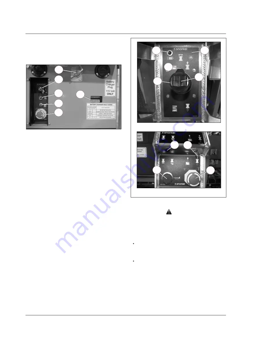
Figure 3 – Upper Controls and Indicators
Danger
Pinch points may exist between moving components.
Death or serious injury will result from becoming
trapped between components, buildings, structures,
or other obstacles. Make sure all personnel stand
clear while operating the aerial platform.
Controls to position the platform are located on the
lower control panel on the chassis and on the upper
control panel in the platform.
Controls to drive the aerial platform are located on the
upper control panel only.
The diagnostic center LCD display is located in the hy-
draulic tray next to the fluid reservoir (refer to Figure 4).
Upper Controls – Top
Upper Controls – Front
13
7
8
9
10
12
11
Controls and Indicators
The operator shall know the location of each control and
indicator and have a thorough knowledge of the function
and operation of each before attempting to operate the
machine.
Figure 2 – Rear of Chassis
1. Battery disconnect switch
2. Control selector/ground operation switch
3. Platform overload protection light
4. Platform raise/lower switch
5. Emergency stop button
6. Battery charger codes
7. Battery condition indicator
8. Interlock switch
9. Joystick
10. Steer switch
11. Drive range switch – S3220E/S3226E/S4726/S4732E
12. Drive/lift selector switch
13. Horn button
1
6
2
5
4
3
3
5


