background image

Introduction

S3219E/S3220E/S3226E/S4726E/S4732E – 1500842 

Introduction

This  manual  covers  the  S3219E,  S3220E,  S3226E, 

S4726E, and S4732E Aerial Work Platforms.

This manual must be stored on the machine at all times.

Read, understand and follow all safety rules and operating 

instructions before attempting to operate the machine.

When contacting Snorkel for service or parts information, 

be sure to include the MODEL and SERIAL NUMBERS 

from the equipment  nameplate. Should the nameplate 

be missing, the SERIAL NUMBER is also stamped on 

the front of the chassis.

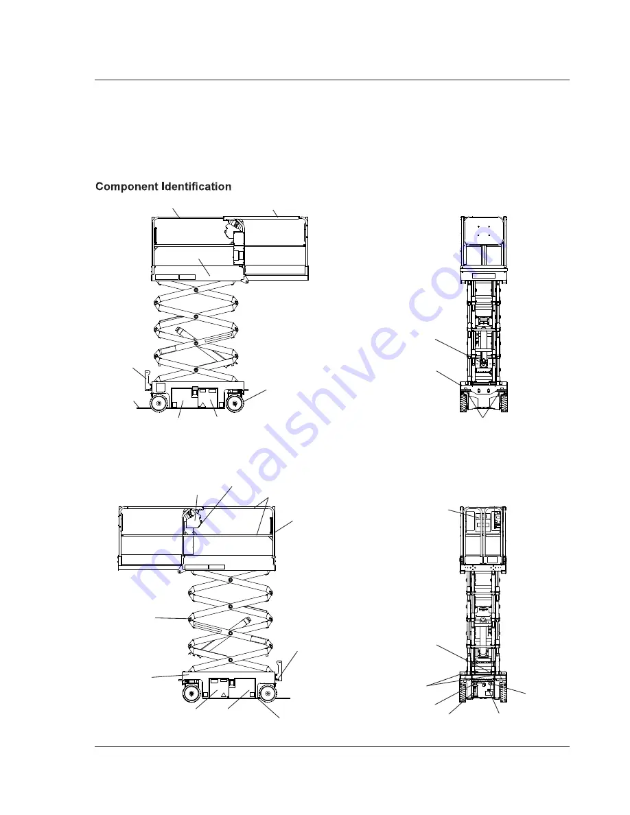
Scissors 

Structure

Right Side

Platform

Guardrails

Left Side

Chassis

Upper 

Controls

Entry

Doors

Platform Extension

Battery Tray

Drive and Steer 

Wheels

Pothole

Protector Skid

Groundstrap

Tie-Down/Lifting

Lugs

Electrical

Power Outlet

Battery Tray

Hydraulic Tray 

Pump/Reservoir/Fluid Filter

Control Valve Tray 

Freewheeling Valve/Brake Release Valve 

Hand Pump/Diagnostic Display

Entry

Step

Toeboards

Lower 

Controls

Operator’s

Manual

Battery Charger 

LED Charge Indicators

Tie-Down/Lifting Lugs

Rear

Front

Forklift 

Pockets

Emergency Lowering

Lever – S3219E

Serial

Number

Power to Platform

Receptacle

Battery

Charger

Receptacle

Emergency Lowering

Handle – S3220E

S3226E, S4726E, S4732E

Summary of Contents for S3219E

Page 1: ......

Page 2: ......

Page 3: ...ve Range Switch S3226E S3220E S4726E S4736E 10 Horn Button 10 Battery Condition Indicator 10 Pre Operation Safety Inspection 10 System Function Inspection 11 Operation 12 Preparing for Operation 12 Lo...

Page 4: ...cate number EC Typenprufung Zertifikat Nr Examen type CE Numero de Certificat Inspeccion tipo CE Numero de certificado Attestato di certificazione CE nr Onderzoek van het type EC Certificaatnummer EU...

Page 5: ...anything to or take anything into the aerial platform that will increase the wind loading such as billboards banners flags etc IN CASE OF EMERGENCY push EMERGENCY STOP switch to deactivate all powere...

Page 6: ...ont View Front View Anchor point Type 1 is rated for one lanyard attachment per loop Refer to machine Specifica tions and platform decals for maximum number of platform occupants Two Lanyards Attached...

Page 7: ...so stamped on the front of the chassis Scissors Structure Right Side Platform Guardrails Left Side Chassis Upper Controls Entry Doors Platform Extension Battery Tray Drive and Steer Wheels Pothole Pro...

Page 8: ...Refer to the machine specifications for the level sensor factory setting Lower the platform and drive to a level surface when the drive lift level sensor alarm sounds The drive lift level sensor syste...

Page 9: ...small branches sway 5 8 0 10 8 28 8 38 9 26 25 35 5 18 24 25 Shrubs with leaves start swaying Wave crests are apparent in ponds or swamps 6 10 8 13 9 38 9 50 0 35 5 45 5 24 5 31 umbrella 7 13 9 17 2 5...

Page 10: ...The diagnostic center LCD display is located in the hy draulic tray next to the fluid reservoir refer to Figure 4 Upper Controls Top Upper Controls Front 13 7 8 9 10 12 11 Controls and Indicators The...

Page 11: ...platform functions will not operate from the lower or upper controls Turn the switch to the upper controls position to operate the aerial platform functions from the upper controls Hold the switch do...

Page 12: ...ch controls the two front wheels to steer the aerial platform To steer to the right engage the interlock switch on the joystick and hold down the right side of the steer switch To steer to the left en...

Page 13: ...welds and structural damage loose hardware hydraulic leaks loose wire connec tions and erratic operation Check for missing or loose parts 5 Hold the ground operation switch downward Test each machine...

Page 14: ...edure to prepare the aerial platform for operation 1 Perform a pre operation safety and system function inspection 2 Close and latch the control valve hydraulic and bat tery trays 3 Place the battery...

Page 15: ...will flash In this case remove the load in excess of rated capacity and cycle the emergency stop button at the upper controls to return to normal operation Extending The platform can be extended and s...

Page 16: ...2 4 m 8 and up to 0 6 km h 0 4 mph when the platformis raisedabove 2 4 m 8 Place the drive range switch in high for normal machine operation Caution The extension deck is free to move when the exten s...

Reviews: