ENGINE (CYLINDERS / HEAD / BASE) 7 - 23
– If there is no leak at the tested location, continue pumping to
maintain pressure and continue with the next item until the leak is
found.
Engine
Check the following:
1. All jointed surfaces and screw/stud threads of engine:
– spark plug base, insulator
– cylinder head
– RAVE valve bellows, piston and housing
– cylinder
– crankcase halves (joint)
– oil injection pump mounting flange (O-ring)
– coolant pump housing
– bleed screws/plugs.
2. Remove cooling system cap.
Check for air bubbles in antifreeze. It indicates defective cylinder
head O-ring or cylinder base gasket.
3. Remove drive pulley then check crankshaft outer seal.
4. Remove rewind starter and magneto system then check
crankshaft outer seal.
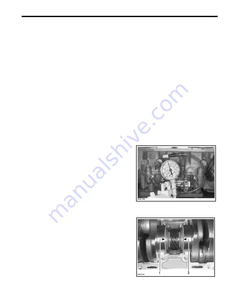
5. Check pump shaft gear oil reservoir.
Pump Shaft Oil Gear Reservoir
Install air pump on adapter and pressurize as shown at right. If
pressure drops, it indicates a defective crankshaft inner seal.
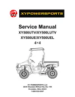
CRANKSHAFT INSTALLED IN UPPER HALF CRANKCASE
1. Crankshaft inner seal on PTO side
2. Crankshaft inner seal on MAG side
Summary of Contents for 600HO
Page 1: ...MY2004 Set up Service and Shop Manual SNOW HAWK 600HO...
Page 28: ...PERIODIC MAINTENANCE 2 11 Symbols used on the NGK spark plugs...
Page 32: ...FUEL SYSTEM 3 3 CARBURET0RS TM 40...
Page 53: ...REWIND STARTER 5 1 REWIND STARTER...
Page 59: ...COOLING SYSTEM 6 1 COOLING SYSTEM 1 2 3 4 5 6 7 8 9 10 11 12 12 12 12 12 12 12 12 12...
Page 67: ...ENGINE CYLINDERS HEAD BASE 7 4 ENGINE CRANKSHAFT AND PISTONS...
Page 69: ...ENGINE CYLINDERS HEAD BASE 7 6 ENGINE TOP END...
Page 89: ...ENGINE CYLINDERS HEAD BASE 7 26...
Page 127: ...FRONT FORK AND TWIN AXIS SKI 11 1 FRONT FORK...
Page 129: ...FRONT FORK AND TWIN AXIS SKI 11 3 FRONT FORK ASSEMBLY...
Page 145: ...REAR SUSPENSION SHOCKS AND TRACK 12 2 REAR SHOCK 53 67 68 69 70...
Page 146: ...REAR SUSPENSION SHOCKS AND TRACK 12 3 MIDDLE SHOCK 54 73 67 70...
Page 149: ...REAR SUSPENSION SHOCKS AND TRACK 12 6 SHOCK EXPLODED VIEW 11 10 11 9 2 12 13 7 6 8 1 5 3 4...


