background image

17

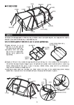
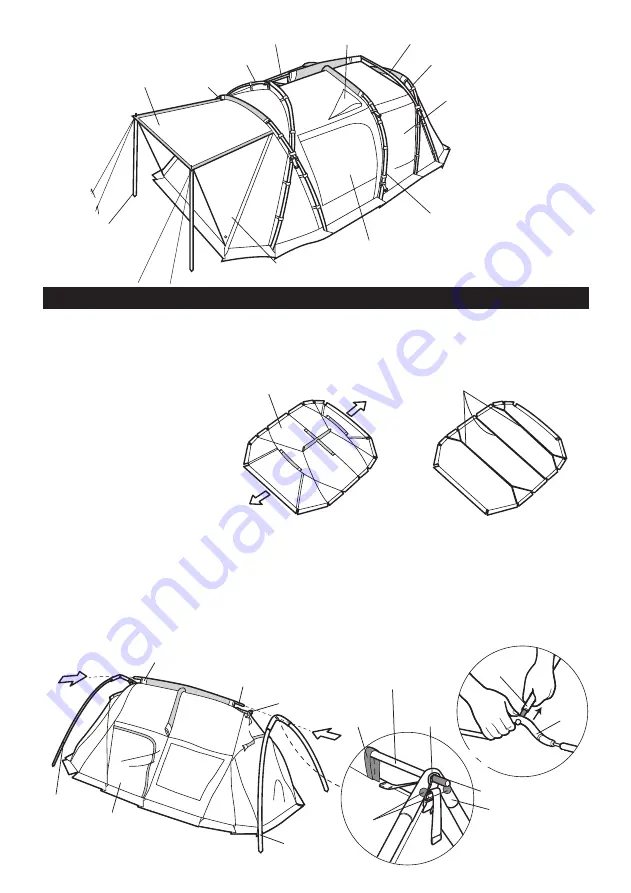
Ridge pole 

A pole

Set A pole on the Ridge pole
in a disassembled state

Set A pole on the Ridge pole
in a disassembled state

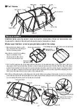
Part Names

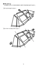
Spread the main body on a flat 

area. Consider the orientation of 
the two doorway panels.

Note: Make sure all three building 

tapes are buckled. If it is 
disconnected, make sure to 
connect them before setup.

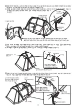
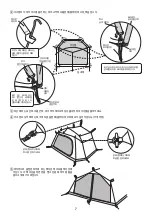
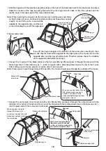
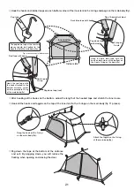
 First, put the dark blue tip of the ridge pole into the sleeve of the dark blue tape in the center. Next, insert the 

ridge pole so that the two dark blue stickers on the A ridge joint part outward. Confirm that the edge of the ridge 
pole is firmly inserted into the end of the A pole joint part, and then insert the center ring as if pushing it all the 
way in and hook it. (Figure A) At this point, please loosen the tape of the center ring without applying tension. 
Next, insert the ridge pole into the A pole on the opposite side.

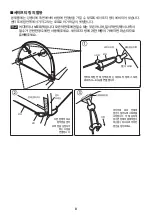
Note: When setting the A pole on the ridge pole, do not set it after connecting all the A poles, and set it on the ridge 

pole while leaving the left and right upper ones apart. (Figure B) By setting it and then starting to raise the A pole, 
you can reduce the stress on the joint and set it up easily.

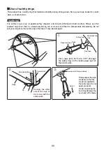
WARNING: Before using the product, check each part for abnormalities. If there are abnormalities, take 
the product to a dealer or Snow Peak Customer Service for inspection or repair.

Setup procedure

Make sure that two or more people take part in the setup.

Ridge pole

A pole

A pole

C pole

C pole

Ventilation

Mesh window

Center Pole

Side door panel

Sidewall

Door panel

Upright pole

Land Lock main body

Door panel

(Entrance / Exit)

Door panel

(Entrance / Exit)

Three building tapes attached to the hem of the main body

Ridge pole

Ridge pole

A pole

Sleeve (dark blue)

Sleeve
(dark blue)

Dark blue

seal

Ridge pole tip (Dark Blue)

Main body

A: Pole joint section

A pole

Center ring

Center ring

(Figure A)

(Figure B)

Summary of Contents for FES-091

Page 1: ...Ver 1 00 Pro RED FRAME EDITION FES 091...

Page 2: ...1 1 7m 2 3 5m 6 2 5m 4 1 5m 2 A 2 C 2 1 1 2 1 1 21cm 31 1 1 2 6 6 1 2 1 1...

Page 3: ...2 2 1kg...

Page 4: ...3 A 2 3 A A 2 A A A A A B 2 A A C C 3 A A A A B...

Page 5: ...4 C A 4 A A A A A C C C C A A A C...

Page 6: ...5 A C O O TP 080 V C A O 7m 3 5m 3 5m 2 5m 1 5m 2 5m C A O V...

Page 7: ...6 O Y Y...

Page 8: ...7 O O 11 O 2 O A O A A O O O...

Page 9: ...8 O 5m 6m...

Page 10: ...9...

Page 11: ...10...

Page 12: ...11 60 Y I Y I PU UV UV...

Page 13: ...12 A PU PU A...

Page 14: ...A 2 C 2 21cm 31 7m 2 3 5m 6 2 5m 4 1 5m 2 2 210D PU 3 000mm UV 210D PU 1 800mm UV 210D PU 68D 210D PU 1 800mm A6061 19mm 22mm 77 35 37cm 73 20 23cm 28 5kg 6 2 507 17 602 TEL 1661 1958 FAX 02 6203 1959...

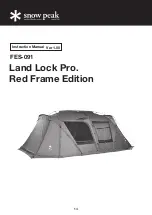
Page 15: ...14 Instruction Manual Ver 1 00 Land Lock Pro Red Frame Edition FES 091...

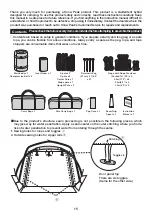
Page 16: ...er penetration to prevent water from entering through the seams 1 Sewing holes for loops and toggles 2 Outside sewing holes for zipper rails Door panel top There are six toggles Same for the other sid...

Page 17: ...nside the tent Choose a flat well drained area with firm ground to pitch the tent The area should have no chance of avalanches landslides wind gusts or sudden flooding It is dangerous if the mud skirt...

Page 18: ...le into the A pole on the opposite side Note When setting the A pole on the ridge pole do not set it after connecting all the A poles and set it on the ridge pole while leaving the left and right uppe...

Page 19: ...he same way as insert a ring pin with a black peg down loop to the tip of the C pole After setting up one C pole please set up the other C pole as well Note Please pass C pole through sleeve little by...

Page 20: ...ough the loop attached to the ring pin on the hem and peg down all the loops inside the room Peg down the rope firmly Use the provided upright pole and a forked end rope to lift the entrance exit door...

Page 21: ...f the Land Lock For the inner tent the side with the logo print at the bottom is the indoor side Please hang the inner tent in the room on the side of the Land Lock without the side door Since there i...

Page 22: ...nt to the O rings and pegs on the main body fly The peg down tape at the rear two places should be hooked to the pegs that hold the main body fly Hook the red tape with the hook attached to the bottom...

Page 23: ...iately Do not put your weight on the safety ring otherwise it may be damaged Connect the other end of the rope to the O ring with the center pole Finally adjust the rope tensioner so that the tension...

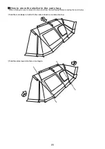
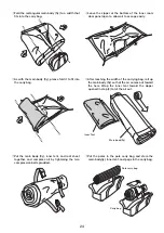
Page 24: ...er in the carry bag When storing be sure to remove the inner tent from the main body before removing the main body Fold the main body in half with the center sleeve as centered on top Fold the sides i...

Page 25: ...inner tent toward the zipper opened in step 4 to let the air out Put the main body fly inner tent and roof sheet together and compress all by tightening the two compression belts provided Put the pole...

Page 26: ...es are connected before taking them down this will make it easier to peg down the next time you set up Fold the pole from the center to the edges If folded from the edge the cord can be overstretched...

Page 27: ...t in a well ventilated area away from heat and moisture Using the zipper when it is covered with mud sand or dust may cause wear or damage Clean the zipper with a brush before use Apply small amounts...

Page 28: ...Rip Stop Shield pigment PU coating Waterproof rating 3 000mm minimum Teflon water repellent finish UV protection treatment Wall 210D Polyester Rip Stop PU coating Waterproof rating 1 800mm minimum Te...

Reviews: