background image

Lit. No. 85757, Rev. 01 

13 

November 15, 2018

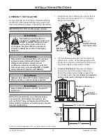
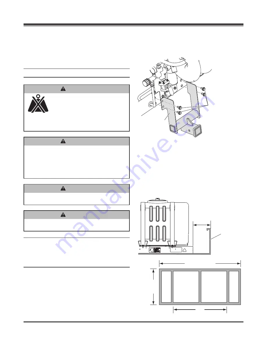
1.  Install the wet boom drop mount onto the rear of 

the frame with four supplied 1/2" x 1" serrated 

fl

 ange hex cap screws.

2.  Lift main assembly using the four lift points and 

position onto vehicle. Center sprayer system left 
to right, then slide the unit forward until the boom 
mount just makes contact with the vehicle.

3. 

Construct Sill Spacer: 

Measure the distance 

from the front end of the sprayer frame to the 
front of the vehicle bed and make a spacer from 
2" x 8" lumber to 

fi

 t that area. 

Failure to install this 

spacer could result in damage to the sprayer.

ASSEMBLY / INSTALLATION

During assembly, check and test completed assembly 
as directed in this manual. Serious injury could result 
from chemical leaks if sprayer is improperly assembled.

IMPORTANT: DO NOT modify sprayer design.

NOTE: To prevent leaks, use a thread-sealing 
compound on all threaded connections. Do 
not use Te

fl

 on

®

 tape, as fragments will clog the 

spray nozzles. Clamped connections may require 
periodic retightening.

INSTALLATION INSTRUCTIONS

Te

fl

 on

®

 is a registered trademark of E. I. du Pont de Nemours and Company.

 WARNING

Always shut vehicle OFF before attempting to 
attach, detach, or service sprayer system.

 WARNING

Never attempt to take a unit off a truck with 
liquid in it.

 WARNING


Overloading could result in an 

accident or damage. Do not exceed 
GVWR or GAWR ratings as found 
on the driver-side vehicle door 

cornerpost. See Speci

fi

 cations section to 

determine maximum volumes of spraying 
material.

 WARNING

New untitled vehicle installation of a sprayer 
system requires National Highway Traf

fi

 c 

Safety Administration altered vehicle 
certi

fi

 cation labeling. Installer to verify that 

full sprayer does not exceed GVWR or GAWR 
rating label and complies with FMVSS.

1/2" x 1" 
Serrated Flange 
Hex Cap Screws

Wet Boom
Drop Mount

Front of 
Truck Bed

Measure distance.

18"

Fit to vehicle.

Measured

Distance

Summary of Contents for Accuspray VSS-1000-1

Page 1: ...nstallation Instructions Original Instructions This manual and instructions are for Accuspray De Icing Systems with serial numbers beginning with 181001 and higher This document supersedes all edition...

Page 2: ......

Page 3: ...Filling 12 INSTALLATION INSTRUCTIONS 13 Assembly Installation 13 Electrical System 15 Wiring Instructions 15 OPERATING INSTRUCTIONS 16 During Operation 16 Before Spraying 17 Adding Brine Liquid 17 Spr...

Page 4: ...Lit No 85757 Rev 01 4 November 15 2018...

Page 5: ..._________________________________________________ Date Purchased _____________________________________________________________________ Outlet Name ______________________________________________ Phone...

Page 6: ...Lit No 85757 Rev 01 6 November 15 2018...

Page 7: ...a potentially hazardous situation that if not avoided could result in death or serious personal injury CAUTION Indicates a potentially hazardous situation that if not avoided may result in minor or mo...

Page 8: ...ice sprayer system Never attempt to take a unit off a truck with liquid in it Do not climb into or ride on the machine WARNING Securely bolt and strap unit into place on the vehicle bed Unit must be s...

Page 9: ...ove ignition key and put the vehicle in PARK or in gear to prevent others from starting the vehicle during installation or service Wear only snug fitting clothing while working on your vehicle or spra...

Page 10: ...ade 5 Grade 8 Size Size Torque ft lb Class 8 8 Class 10 9 Torque ft lb Class 8 8 Class 10 9 Inch Fasteners Grade 5 and Grade 8 SAFETY TORQUE CHART CAUTION Read instructions before assembling Fasteners...

Page 11: ...alation In case of poisoning from ingestion or inhalation If the victim has collapsed or is not breathing call 911 Otherwise 1 If you are the victim immediately seek assistance from nearby personnel b...

Page 12: ...e control material package labeling including Safety Data Sheet requirements FIRST TIME FILLING 1 Install the sprayer and any optional equipment See the Installation Instructions section of this manua...

Page 13: ...thread sealing compound on all threaded connections Do not use Teflon tape as fragments will clog the spray nozzles Clamped connections may require periodic retightening INSTALLATION INSTRUCTIONS Tef...

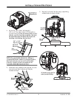
Page 14: ...he frame to prevent buckling or deforming the truck bed NOTE Pay special attention when drilling or clamping dissimilar metals to aluminum bodies Galvanic corrosion can occur if not handled properly C...

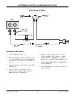
Page 15: ...female spade red wire to the switch Leave the black wire for Step 5 3 Route the power harness from the battery to the switch control 4 Attach the red lead to the POSITIVE side of the battery and the b...

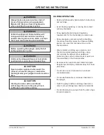
Page 16: ...ontact with any chemicals Know applicable licensing and regulatory requirements for the chemical s you plan to use Know emergency procedures before handling chemicals Carefully review the Chemical Saf...

Page 17: ...e handle to the appropriate position OPEN for the spray boom CLOSED for the spray wand 4 When ready to spray turn the pump switch to the ON position 5 If using the spray wand point the wand in the des...

Page 18: ...r than 16 to drive the vehicle with the filled sprayer attached Make sure sprayer is securely attached to vehicle Exercise caution in vehicle handling when driving with filled sprayer to avoid loss of...

Page 19: ...s in the charts below are based on manufacturer s numbers If your flow is uncharacteristically slow see the Troubleshooting and Maintenance sections Nozzle Selection Suggested Operating Range 30 40 ps...

Page 20: ...69 46 14 43 07 40 37 38 35 88 34 32 3 40 1 00 74 25 67 5 61 88 57 11 53 04 49 5 46 04 43 68 41 25 39 08 37 13 50 1 12 82 1 75 5 69 3 63 97 59 4 55 44 51 98 48 92 46 2 43 77 41 58 GPM gallons per minu...

Page 21: ...as necessary When reassembling nozzles make sure that the nozzle holes are in line with the boom Failure to align the nozzle holes will result in inconsistent brine application MAINTENANCE NOTE To pr...

Page 22: ...ing Refer to Problem 1 Pump doesn t run Dead or dying battery Charge or replace battery Obstructed nozzle Remove and clean Teflon is a registered trademark of E I du Pont de Nemours and Company WARNIN...

Page 23: ...Lit No 85757 Rev 01 23 November 15 2018...
Page 24: ...rovement policy to change construction or design details and furnish equipment when so altered without reference to illustrations or specifications used TrynEx International or the vehicle manufacture...

Reviews: