background image

Lit. No. 86834, Rev. 00 

12 

November 15, 2018

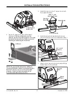
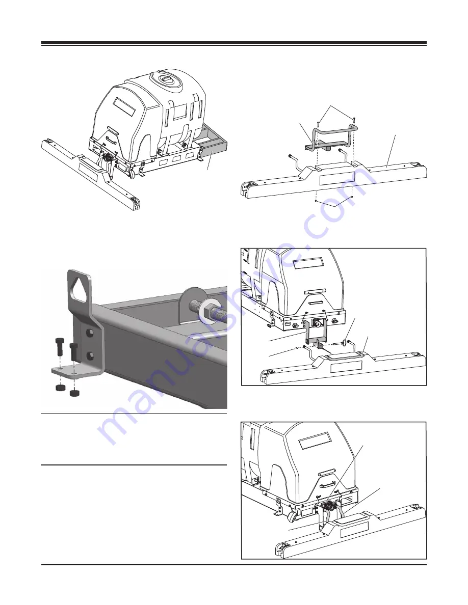
5.  Install the boom onto the 2" receiver mount with 

the supplied hardware.

6.  Install the spray boom assembly with receiver 

mount into the wet boom mount installed in Step 1.

7.  Plug the boom hoses into the pump output 

fi

 ttings 

located below the shut-off valve.

Boom
Hose

Boom 
Hose

Shut-Off
Valve

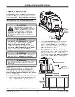
4.  Secure the sprayer into place with supplied 

hardware. 

If the mounting holes are not 

directly over the truck box supports, the truck 
bed must be braced to the frame to prevent 
buckling or deforming the truck bed.

NOTE: Pay special attention when drilling or 
clamping dissimilar metals to aluminum bodies. 
Galvanic corrosion can occur if not handled 
properly. Contact vehicle manufacturer for 
recommended attachment practices.

INSTALLATION INSTRUCTIONS

5/16" x 1-3/4" 

Hex Cap Screws

Receiver 
Mount

5/16" Locknuts

Spray Boom

Wet Boom
Mount

Receiver

Mount

5/8" x 5-1/2" 
Hitch Pin

2-5/16" 
Hairpin Clip

Lift Point

Frame Spacer
Built to Fit

Summary of Contents for Accuspray VSS-2000

Page 1: ...spray De Icing Systems VSS 2000 and VSS 3000 Owner s Manual and Installation Instructions Original Instructions This document supersedes all editions with an earlier date CAUTION Read this document be...

Page 2: ...Lit No 86834 Rev 00 2 November 15 2018...

Page 3: ...nesses 13 Vehicle Harness 13 Control Power Harness 13 Electrical System Wiring Instructions 14 Electrical System 14 Wiring Instructions 14 OPERATING INSTRUCTIONS 15 During Operation 15 Before Spraying...

Page 4: ..._________________________________________________ Date Purchased _____________________________________________________________________ Outlet Name ______________________________________________ Phone...

Page 5: ...amiliar with and inform users about the warning and caution labels on the machine If labels are missing or cannot be read call 1 800 SALTERS 725 8377 T 20317 CAUTION UTION WEAR SAFETY GOGGLES WHEN OPE...

Page 6: ...not climb into or ride on the machine WARNING Securely bolt and strap unit into place on the vehicle bed Unit must be strapped down and bolted into position before operating or transporting WARNING Ve...

Page 7: ...o prevent others from starting the vehicle during installation or service Wear only snug fitting clothing while working on your vehicle or sprayer system Do not wear jewelry or a necktie and secure lo...

Page 8: ...de 5 Grade 8 Size Size Torque ft lb Class 8 8 Class 10 9 Torque ft lb Class 8 8 Class 10 9 Inch Fasteners Grade 5 and Grade 8 SAFETY TORQUE CHART CAUTION Read instructions before assembling Fasteners...

Page 9: ...ul effects Bring the chemical label for reference Poisoning by Ingestion or Inhalation In case of poisoning from ingestion or inhalation If the victim has collapsed or is not breathing call 911 Otherw...

Page 10: ...and adhere to manufacturer s ice control material package labeling including Safety Data Sheet requirements FIRST TIME FILLING 1 Install the sprayer and any optional equipment See the Installation Ins...

Page 11: ...ments will clog the spray nozzles Clamped connections may require periodic retightening 1 Secure the wet boom mount assembly onto the rear of the frame with the supplied hardware INSTALLATION INSTRUCT...

Page 12: ...hardware If the mounting holes are not directly over the truck box supports the truck bed must be braced to the frame to prevent buckling or deforming the truck bed NOTE Pay special attention when dri...

Page 13: ...er Harness WHITE BLACK YELLOW RED GREEN BLUE Anderson Block 4 POSITIVE ORANGE GREEN BLUE YELLOW BUMPER PLUG CONTROL OUTPUTPLUG Connect to control mating half NEGATIVE Black to battery ring terminal NO...

Page 14: ...Once the control is mounted install the harness connectors into the back of the control Leave some slack in the harness so that the connectors are not under any strain Tie wrap all harnesses to proper...

Page 15: ...o contact with any chemicals Know applicable licensing and regulatory requirements for the chemical s you plan to use Know emergency procedures before handling chemicals Carefully review the Chemical...

Page 16: ...ition 2 Fill the sprayer with liquid through the port on the top of the tank 3 When ready to spray turn the pump switch to the ON position 4 When done spraying be sure to turn the pump switch to the O...

Page 17: ...age to drive the vehicle with the filled sprayer attached Make sure that the sprayer is securely attached to vehicle Exercise caution in vehicle handling when driving with filled sprayer to avoid loss...

Page 18: ...icing Application rates in the charts below are based on manufacturer s numbers If your flow is uncharacteristically slow see the Troubleshooting and Maintenance sections Nozzle Selection Suggested Op...

Page 19: ...69 46 14 43 07 40 37 38 35 88 34 32 3 40 1 00 74 25 67 5 61 88 57 11 53 04 49 5 46 04 43 68 41 25 39 08 37 13 50 1 12 82 1 75 5 69 3 63 97 59 4 55 44 51 98 48 92 46 2 43 77 41 58 GPM gallons per minu...

Page 20: ...as necessary When reassembling nozzles make sure that the nozzle holes are in line with the boom Failure to align the nozzle holes will result in inconsistent brine application MAINTENANCE NOTE To pr...

Page 21: ...Refer to Problem 1 Pump doesn t run Dead or dying battery Charge or replace battery Obstructed nozzle Remove and clean Teflon is a registered trademark of E I du Pont de Nemours and Company WARNING Al...

Page 22: ...Lit No 86834 Rev 00 22 November 15 2018 Large Lot START END LARGE LOT VEHICLE TRACK DE ICING EXAMPLES...

Page 23: ...Lot DE ICE ENTRANCE AREA DE ICE AREA DE ICE AREA DE ICE ENTRANCE AREA DE ICE AREA DE ICE AREA DE ICE AREA ENTRANCE TRAFFIC FLOW Vehicles will track de ice and anti ice solutions around lot while movi...

Page 24: ...rovement policy to change construction or design details and furnish equipment when so altered without reference to illustrations or specifications used TrynEx International or the vehicle manufacture...

Reviews: