15
© Trynex International 2012 (REV A) F50734
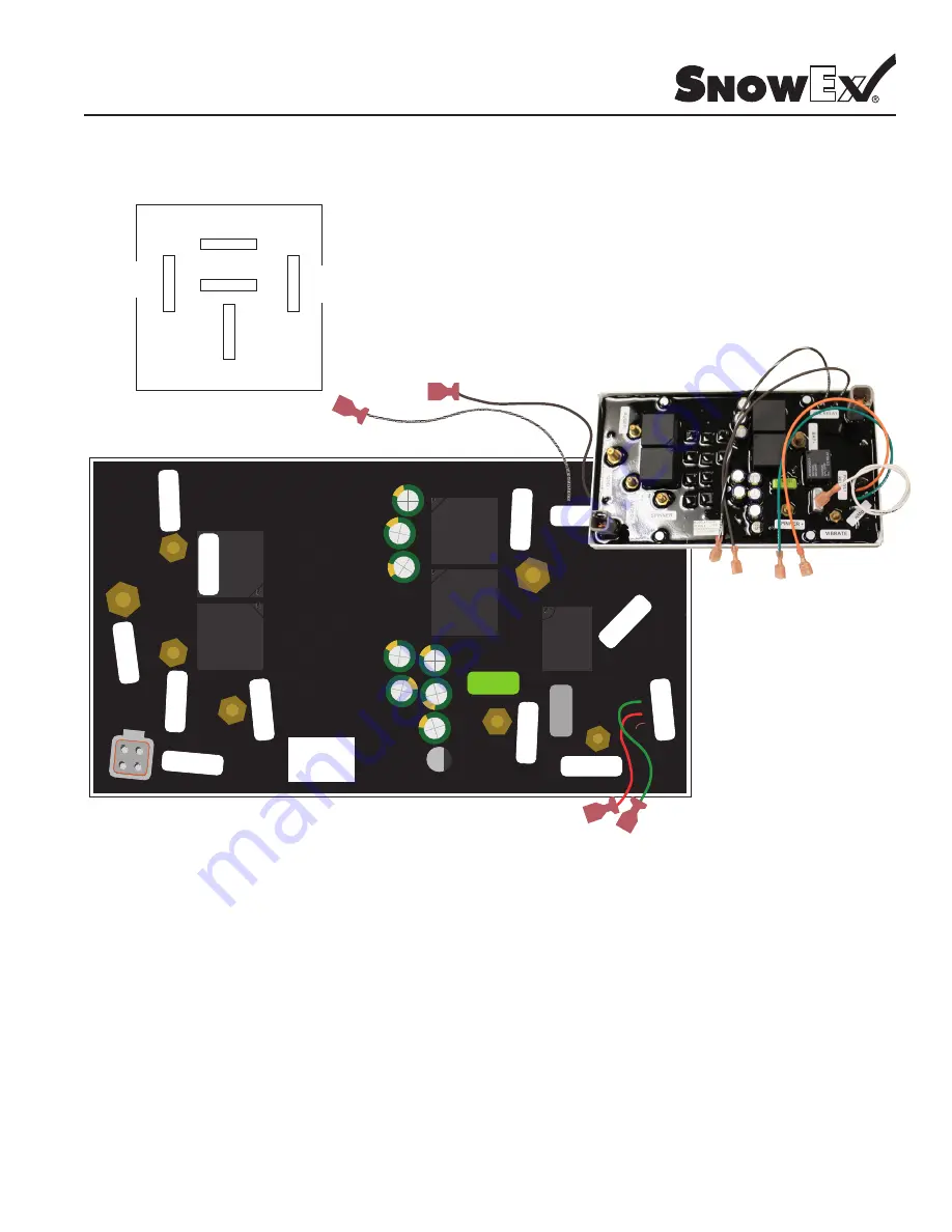
Control Diagram
Model # SP-9500X
D6083 30 AMP Relay
CE
1
05
C
(M
)
CE
105
C
(M
)
CE
1
05
C
(M
)
CE
1
05
C
(M
)
CE 105 C (M
)
CE 1
05 C
(M
)
CE
1
05
C
(M
)
CE
1
05
C
(M
)
220
HFC.
0W2
VIBRATE
AUX RELAY
Passed E.T.
1060
S
GND -
BA
T +
PWM
PRE
WE
T
RELA
Y
SPINNER -
AUGER +
AUGER -
������� REV: ��
I IIIII I IIII IIIII IIIII II I III II
��������
Model # F50541
Serial # 0000
TRYNEX INTERNATIONAL
1-800-725-8377
F50541 Spreader Control
Wire Connections
“AUX RELAY”
Brown/White Wire
“AUX RELAY”
Brown Wire
F50563
Red Wire (w/ Spade)
F50681
Wire from “BAT +”
Empty
Small Gray Plug: Plugged with Sealed Blank Connector
GND -: Light Harness Black Wire; Spreader Harness Black Wire; Vibrator Harness Black Wire.
Auger +: Auger Harness White Wire.
Auger -: Auger Harness Black Wire.
Spinner -: Spinner Harness Black Wire.
S: Spinner Harness Red Wire.
Vibrate: Vibrator Harness Red Wire.
Bat +: Relay Wire (Red); Spreader Harness Red Wire
Large Gray Plug: Pendant Harness Gray Connector.
Relay: see diagram above.
Other: Pendant Harness Red Wire Connected to Light Harness Red Wire with Round Butt Connector.


