© Trynex International 2009 L1102
5 — 23
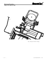
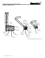
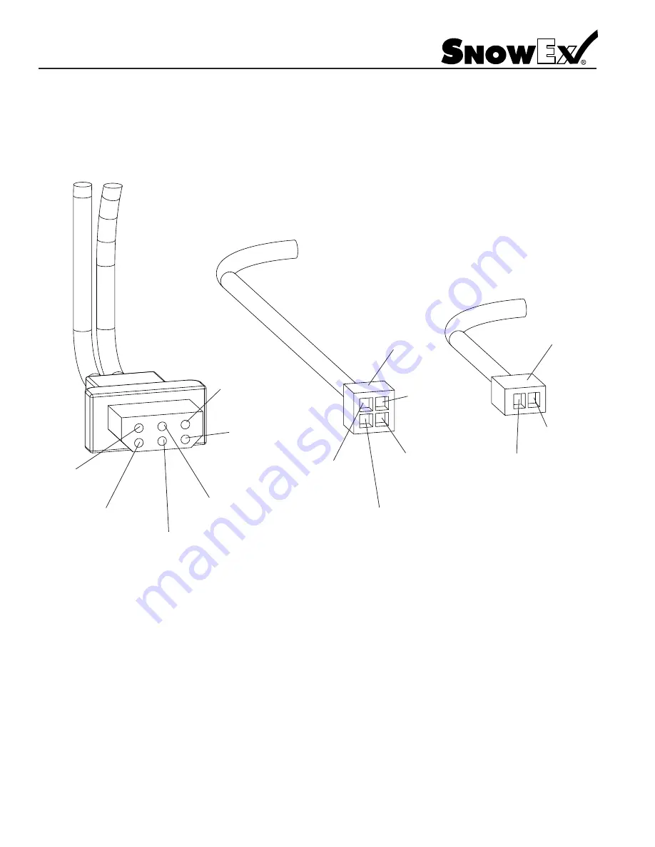
Vehicle Harness Circuit Diagram
Model # SP-3000/SP-6000
VIBRATOR
Black Negative (–)
VIBRATOR
White Positive (+)
AUGER
Green Negative (–)
AUGER
Red Positive (+)
SPINNER
Black Negative (–)
SPINNER
White Positive (+)
Red
Positive (+)
White Wire
Black
Negative (–)
Black Wire
Anderson
Block
(2) Pos
Anderson
Block
(4) Pos
AUGER OUTPUT
(housing)
Red Positive (+)
Red Wire
AUGER OUTPUT
(housing)
Black Negative (–)
Green Wire
SPINNER OUTPUT
(housing)
Red Positive (+)
White Wire
SPINNER OUTPUT
(housing)
Black Negative (–)
Black Wire
BUMPER
PLUG
CONTROL
OUTPUT PLUG
SPINNER/AUGER
CIRCUIT
VIBRATOR
CIRCUIT
OUTPUT
* NOTE: Reference Bumper Plug for Color Code
Summary of Contents for Vee Pro 3000
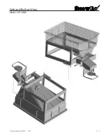
Page 8: ...Trynex International 2009 L1102 5 8 Side and Bottom View Model SP 3000...
Page 9: ...Trynex International 2009 L1102 5 9 Side and Bottom View Model SP 6000...
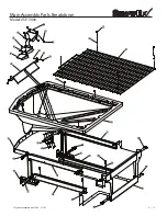
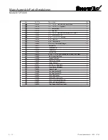
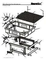
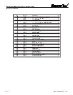
Page 11: ...Trynex International 2009 L1102 5 11 Main Assembly Parts Breakdown Model SP 3000...
Page 13: ...Trynex International 2009 L1102 5 13 Main Assembly Parts Breakdown Model SP 6000...
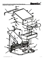
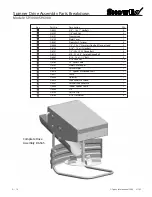
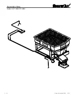
Page 18: ...Trynex International 2009 L1102 5 18 Assembly View Model SP 3000 SP 6000...
Page 39: ...THIS PAGE INTENTIONALLY LEFT BLANK Trynex International 2009 L1102 5 39...
Page 40: ...THIS PAGE INTENTIONALLY LEFT BLANK Trynex International 2009 L1102 5 40...
Page 41: ...THIS PAGE INTENTIONALLY LEFT BLANK Trynex International 2009 L1102 5 41...

