© Trynex International 2009 L1102
5 — 33
Operating the Spreader
(continued)
BAFFLE INSTRUCTIONS
•
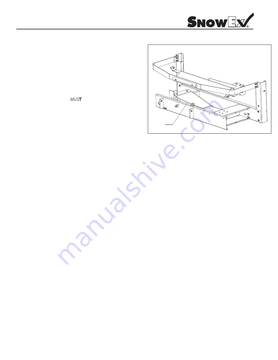
The Vee Pro 3000/6000 uses a single baffle design over the
auger area. This baffle is used for salt/sand mixtures of 50% sand
and 50% salt.
•
WARNING: Always disconnect power source before attempting to
remove material baffle.
•
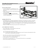
The main baffle (D 6577)
MUST
never be removed from
its original factory installed position unless the unit is being
serviced or installing Optiflow Kit.
WARNING PROTECTION
•
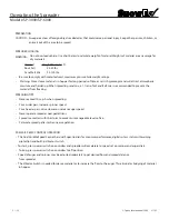
If audible beeping occurs, read display to identify problem: if display reads “OL” (overload) or “OH” (overheat), shut controller
down and carefully clear jammed auger. If display reads “E1“ this means there is a dead short in system. Do not use until
problem is corrected. If display reads “E0”, this means that the motor is not getting any power. Check all connections. If display
reads “LB” the vehicle battery is extremely low and could damage the system. Also check for poor connections which also can
cause the same error code.
•
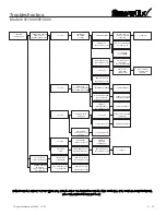
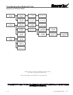
If there are any problems while operating the spreader, refer to Troubleshooting Guide.
AUTO-REVERSE “AR” FUNCTION
•
If your controller displays “OL” this could indicate a jammed auger.
•
To engage the Auto-Reverse “AR” function:
Step 1:
Shut the Main Power Switch OFF for 3 seconds.
Step 2:
Turn the Main Power Switch ON. When the machine starts back up the “AR” sequence will automatically start and the
auger will reverse for several rotations to clear the jam.
•
After a pause of several moments, the auger will automatically return to correct rotation.
•
If the jam is still not cleared, the controller will again display “OL”.
•
You may repeat Steps 1 & 2 for a second and third time.
•
If after the third try the controller displays “OL” — you must extract the material that is causing the problem.
•
Follow all warning directions when clearing jams.
D6577
Model # SP-3000/SP-6000
Summary of Contents for Vee Pro 3000
Page 8: ...Trynex International 2009 L1102 5 8 Side and Bottom View Model SP 3000...
Page 9: ...Trynex International 2009 L1102 5 9 Side and Bottom View Model SP 6000...
Page 11: ...Trynex International 2009 L1102 5 11 Main Assembly Parts Breakdown Model SP 3000...
Page 13: ...Trynex International 2009 L1102 5 13 Main Assembly Parts Breakdown Model SP 6000...
Page 18: ...Trynex International 2009 L1102 5 18 Assembly View Model SP 3000 SP 6000...
Page 39: ...THIS PAGE INTENTIONALLY LEFT BLANK Trynex International 2009 L1102 5 39...
Page 40: ...THIS PAGE INTENTIONALLY LEFT BLANK Trynex International 2009 L1102 5 40...
Page 41: ...THIS PAGE INTENTIONALLY LEFT BLANK Trynex International 2009 L1102 5 41...

