background image

765042231 Rev.000


SNOWFLAKE SBU 15 / 20 / 40 


Service manual 


Summary of Contents for 965780515

Page 1: ...1 765042231 Rev 000 SNOWFLAKE SBU 15 20 40 Service manual...

Page 2: ...14 CORE PROBE 14 TEMPERATURES 15 LENGTH 15 CONTROL PANEL 16 POSITIVE SOFT QUICK COOLING KEY 16 NEGATIVE QUICK COOLING KEY 16 PROGRAMME 18 PRE COOLING CYCLE 19 CORE PROBE POSITIVE SOFT QUICK COOLING CY...

Page 3: ...EEL MAINTENANCE 30 DISCONTINUED USE 31 EXTRAORDINARY MAINTENANCE 31 MAINTENANCE OF PANEL BOARD 31 CONDENSING SYSTEM MAINTENANCE 32 ENERGY CONSUMPTION CHART 33 WIRING DIAGRAM PLATE 34 EC declaration of...

Page 4: ...failure to observe even partially the indications found in this manual Please remember that no reproductions of this handbook are allowed Due to our constant technological updating and research the f...

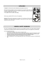
Page 5: ...the environment GENERAL SAFETY WARNINGS The user is responsible for operations carried out on the equipment which do not comply with the indications in this manual and periodic training of all personn...

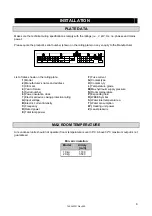
Page 6: ...ectrical device casing protection rating A Input voltage B Electric current intensity C Frequency D Rated power E Total lamp power F Fuse current G Coolant type H Coolant q ty L Temperature grade M Ma...

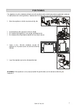
Page 7: ...ance onto the required working site Avoid locations with exposure to direct sunlight Do not place the appliance in hot poorly ventilated rooms Do not place the refrigerated compartment near heat sourc...

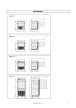
Page 8: ...8 765042231 Rev 000 DIMENSIONS SBU 15 HL SBU 20 HL SBU 20 HT SBU 40 HT...

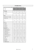
Page 9: ...30V 1N 230V 1N 230V 1N 400V 3N Frequency Hz 50 50 50 50 Intensity A 5 2 6 2 6 2 6 Power input W 1000 1350 1350 3200 Refrigerating unit Refrigerating power W 887 887 887 3136 Evaporation temperature C...

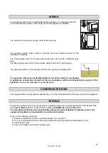
Page 10: ...or operators arising from the non compliance with the and tampering to any part of the appliance electric thermodynamic or hydraulic plant CONDENSATE DRAIN The equipment has a condensation collection...

Page 11: ...iration if respiration has stopped or is about to stop In case of cardiac arrest give external cardiac massage Seek immediate medical attention Skin use water to remove ice from affected areas Remove...

Page 12: ...ed with domestic waste Make the appliance totally unusable by removing the power cable and any door locking mechanisms in order to avoid the risk of anyone being trapped inside DISMANTLING OPERATIONS...

Page 13: ...density water contents fat contents d starting temperature e thermal conduction inside the foodstuffs Positive Negative quick cooling time depends on type of foodstuffs to be processed In general the...

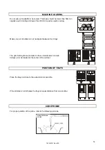
Page 14: ...grid holding frame included in those models which include trolleys is to be located at the center of the cabinet POSITION OF TRAYS Place the trays as close to the evaporator as possible If the cabine...

Page 15: ...ture of 90 C in positive chilling from 90 C to 3 C and in negative chilling from 90 C to 18 C LENGTH Cooled or frozen processed foodstuffs may be stored in a refrigerator for 5 days of processing with...

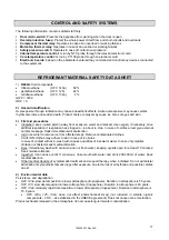
Page 16: ...seconds you can set the card to Off from any mode CHILL POSITIVE SOFT QUICK COOLING KEY With the card on stop press this key once to select a positive soft quick cooling cycle FREEZE NEGATIVE QUICK C...

Page 17: ...ion or when warning that the needle is not inserted TIME LED It is on during a time controlled cycle and blinking during selection STORING LED It is on during the stage after blast chill preservation...

Page 18: ...ck cooling 22 C at the end of the negative quick cooling Cooling time FOODSTUFF SHEET MAX LOAD PRODUCT THICKNESS QUICK COOLING TIME ROOM TEMPERATURE CORE TEMPERATURE FIRST COURSES Bechamel GN1 1 h60 6...

Page 19: ...ing QC Press or within 15 seconds to change the value Use the and keys to change the value Press the key to start the cycle The and icons remain steady the test is run to verify the insertion of the c...

Page 20: ...the e keys to change the value Press the key to start the cycle The HARD and icons remain steady the test is run to verify the insertion of the core probe The cycle is run when the test is completed...

Page 21: ...main steady the test is run to verify the insertion of the core probe As the needle probe is not inserted the test is not completed successfully and the time controlled cycle is launched The and icons...

Page 22: ...verify the insertion of the core probe As the needle probe is not inserted the test is not completed successfully and the time controlled cycle is launched The HARD and icons remain on The display sho...

Page 23: ...sfully and the time controlled cycle is launched The and icons remain steady The display shows the remaining time of the cycle Press or to change the value Use the e keys to change the value DEFROSTIN...

Page 24: ...display shows the value 0 Press within 15 seconds to set the password 19 CHILL Press CHILL or do not operate 15 sec The display shows PA Press the and keys for 4 seconds The display shows CA1 Use the...

Page 25: ...ed a negative blast chilling and preservation cycle HARD Hard quick cooling led if it is lit hard chilling in progress if it flashes you have selected a hard chilling and preservation cycle Blast chil...

Page 26: ...is not yet ready for inserting the food stuff LED on off if it is lit equipment in standby if it is off equipment in on LED Celsius degree if it is lit the temperatures will be measured in degrees Cel...

Page 27: ...fects the instrument will store the alarm id Open door alarm This alarm does only occur if the door is left open for more than 1 minute Remedies verify the state of the door Make sure the door is clos...

Page 28: ...ck the integrity of the probe check the connection instrument probe check the cabinet temperature Effects equipment in standby the blast chill cycles with probe are timed during positive blast chillin...

Page 29: ...mponents stainless stell plastic or painted parts with lukewarm water and detergent Then rinse and dry without using abrasives or chermical solvents Do not wash the appliance by spraying high pressure...

Page 30: ...ANCE By stainless steel we mean INOX AISI 304 steel We recommend following the instructions below for the maintenance and cleaning of stainless steel parts This is of the utmost importance to ensure t...

Page 31: ...unit with a nylon cloth to protect it from dust In case of appliances with remote control if you decide to turn it off remember to put the switch off also in the remote control EXTRAORDINARY MAINTENA...

Page 32: ...electrical panel box along the slide Mod 101L Remove the closing panel screws Unhook the dashboard pulling it forward Remove the closing panel CONDENSING SYSTEM MAINTENANCE Mod 31 51 101 To access the...

Page 33: ...2 Cooling temperature C 65 10 Time cycle chilling min 120 Energy consumption for chilling kWh kg 0 124 0 089 0 089 0 137 Frozen full load capacity kg 8 12 12 25 Freezing temperature C 65 18 Time cycle...

Page 34: ...20 DOOR ANTICONDENSING RESISTOR 79A MULTIPOINT NEEDLE CORE PROBE 21 DEFROST RESISTANCE 79B MULTIPOINT PROBE RESISTANCE 21A DEFROST RESISTANCE 80 PTC RESISTANCE FOR COMPRESSOR CASING 25 TRANSFORMER 86...

Page 35: ...TICONDENSING RESISTOR 79A MULTIPOINT NEEDLE CORE PROBE 21 DEFROST RESISTANCE 79B MULTIPOINT PROBE RESISTANCE 21A DEFROST RESISTANCE 80 PTC RESISTANCE FOR COMPRESSOR CASING 25 TRANSFORMER 86 CONDENSER...

Page 36: ...TICONDENSING RESISTOR 79A MULTIPOINT NEEDLE CORE PROBE 21 DEFROST RESISTANCE 79B MULTIPOINT PROBE RESISTANCE 21A DEFROST RESISTANCE 80 PTC RESISTANCE FOR COMPRESSOR CASING 25 TRANSFORMER 86 CONDENSER...

Page 37: ...37 765042231 Rev 000 EC declaration of conformity...

Reviews: