background image

Mini Dart 
Assembly instruction………………………………………………….

SoaringModels 


1.


Equipment, materials and tools for assembly 


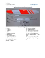
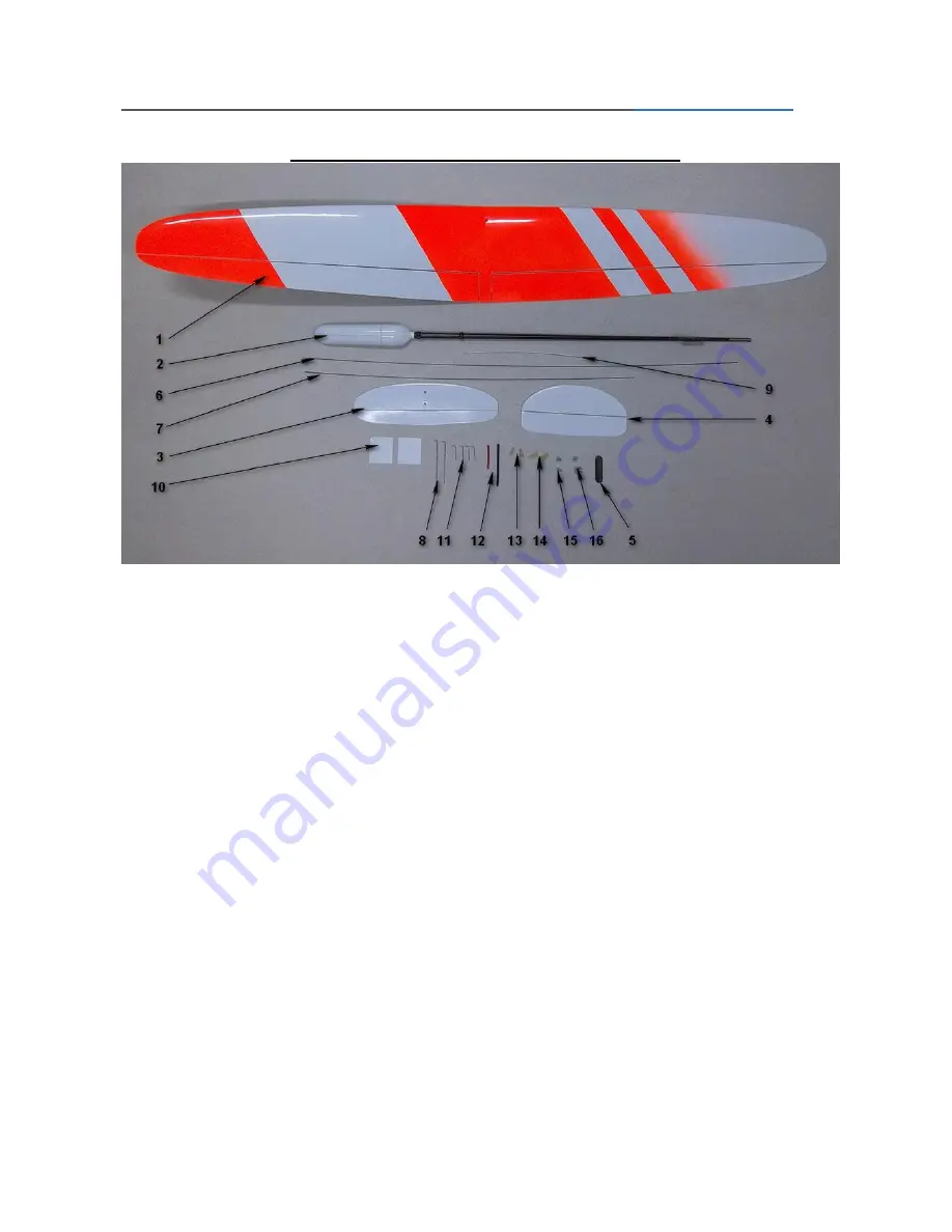
Picture 1.1.  Supply kit 

1 – Wing; 
2 – Fuselage; 
3 – Stabilizer; 
4 – Keel; 
5 – Dowel for throwing; 
6 – Rudder rod; 
7 – Elevating rudder rod; 
8 – Aileron rod (2 pieces); 
9 – Bowden tube; 
10 – Hatches of the aileron 
machines (2 pieces); 

11 – Rod tips (4 pieces); 
12 – Thermal shrinkage; 
13 – Plumage pylons (2 pieces); 
14 – Aileron pylons (2 pieces); 
15 – Screws for mounting of the 
stabilizer М2*6 (2  2 spare 
ones) 
16 – Screws for mounting of the 
wing М2,5*8 и М2,5*10 (1 spare 
set) 


Summary of Contents for MINI-DART

Page 1: ...Mini Dart Assembly instruction 1 Equipment materials and tools for assembly 2 2 Assembly 3 3 Setting of the model 11...

Page 2: ...wel for throwing 6 Rudder rod 7 Elevating rudder rod 8 Aileron rod 2 pieces 9 Bowden tube 10 Hatches of the aileron machines 2 pieces 11 Rod tips 4 pieces 12 Thermal shrinkage 13 Plumage pylons 2 piec...

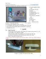
Page 3: ...ulator 250 300 mAh recommended sizes 17 30 mm 2 Servo drivers Power HD 1440 or Dymond D 47 4 pieces 3 6 channel receiver 2 Assembly 2 1 Insert of pylons Cut the grooves for the pylons with a knife as...

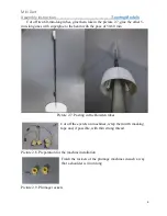
Page 4: ...f the ailerons Picture 2 3 Pasting in the pylons of the elevating rudder 2 2 Pasting in the keel Set up the wing and the stabilizer insert the keel into the groove set it vertically and carefully pour...

Page 5: ...or Bowden tubes transmitter antennas and wires of the aileron machines with a pencil drill with a 2 mm drill and finish with a needle file Picture 2 5 Rework of the nozzle Glue the tip to one of the e...

Page 6: ...glue to the beam with the pace of 50 60 mm Picture 2 7 Pasting in the Bowden tubes Cut off the eyelets on machines wrap them with masking tape and if possible with thin strong thread Picture 2 8 Prepa...

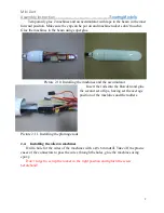
Page 7: ...nes and the accumulator Insert the rods into the Bowden and glue the second set of tips having set the average position of the machines and the rudders Picture 2 11 Installing the plumage rods 2 4 Ins...

Page 8: ...instruction SoaringModels 8 Picture 2 12 Installing the aileron machines 2 5 Inserting the dowel for throwing Round the dowel with sandpaper until the shape is comfortable for you to use Picture 2 13...

Page 9: ...ure 2 14 Inserting the dowel for throwing At the distance of 15 mm from the wingtip drill a hole for the dowel and then finish it with a needle file Spread the holes inside with epoxy insert the dowel...

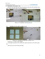
Page 10: ...with a marker bend the edges of the rods with pliers Picture 2 15 Installation of the aileron rods 2 7 Installation of the aileron machine covers Picture 2 16 Installation of the aileron machine cover...

Page 11: ...s in the pylons by the pieces of the thermal shrinkage except the elevating rudder rod Picture 2 17 Fixation of the rods in the pylons Stretch the wires of the aileron machines out through the hole in...

Page 12: ...e model Set up the receiver and establish the alignment at the distance of 50 52 mm from the front edge We recommend setting up 5 flight modes on the transmitter Starting 0 5mm up High speed 0 Regular...

Reviews: