SOCATA
MODEL TB 20
SECTION 7
DESCRIPTION
The content of this document is the property of
socata
. It is supplied in
confidence and commercial security of its contents must be maintained.
It must not be used for any purpose other than that for which it is supplied, nor
may information contained in it be disclosed to unauthorized persons. It must not
be reproduced nor transmitted in any form in whole or in part without permission
in writing from the owners of the Copyright.
Information in this document is subject to change without notice.
© 1988, 1991, 1992, 1994 to 1996, 1997, 2000 -
socata
- All rights reserved
June 30, 1988
Revision 8
7.8
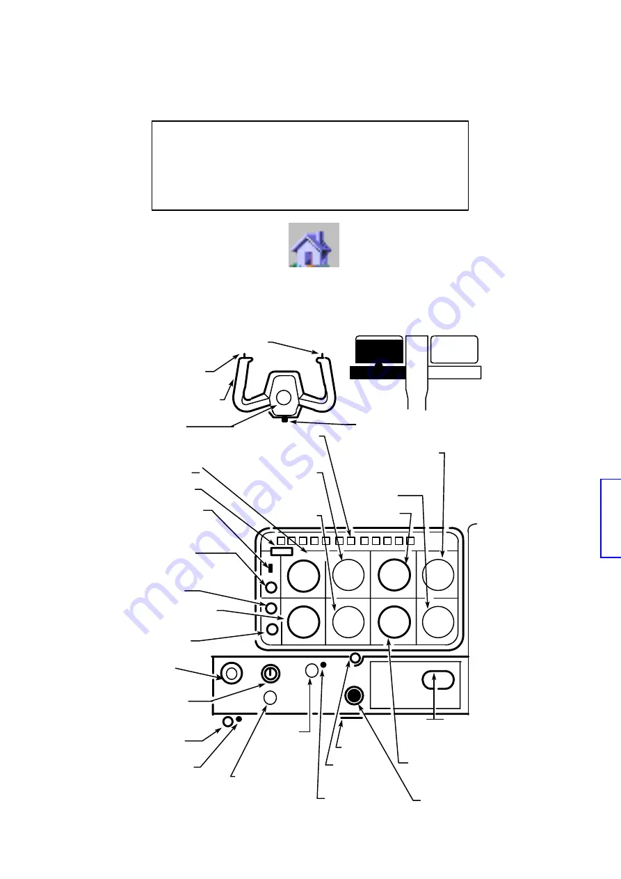
Figure 7.1 – EXAMPLE OF INSTRUMENT PANEL AND L.H. SUBPANEL
HANDLE
MAP READING LIGHT SWITCH
(If installed)
EMERGENCY LIGHTING
CONTROL
EMERGENCY
GEAR CONTROL AND
CIRCUIT BREAKERS
PANEL LIGHTING
VOR / ILS INDICATOR
(If installed)
MAP READING LIGHT
(If installed)
CLOCK / STOP WATCH
(If installed)
PILOT’S AIR
OUTLET
VERTICAL SPEED
INDICATOR
PARKING
BRAKE KNOB
CONTROL
WHEEL TUBE
LANDING GEARS
CONFIGURATION
AND CONTROLS
EMERGENCY
LANDING GEAR
CONTROL
MAGNETO /
START
SELECTOR
AIRSPEED
INDICATOR or
TRUE AIRSPEED
INDICATOR
NORMAL LIGHTING
CONTROL
BANK INDICATOR
INSTRUMENTS
AND RADIO LIGHTING
CONTROL
EMERG. RADIO
BEACON SWITCH
LIGHTS
)
VACUUM
GAGE LIGHTING
ALTIMETER
ALTERNATE
STATIC SOURCE
VALVE (If installed)
VACUUM
GAGE
(If installed)
ADF INDICATOR
(If installed)
HORIZONTAL ATTITUDE
INDICATOR (If installed)
HEADING
INDICATOR
(If installed)
RADIO CALL
PUSH–TO–TALK
SWITCH
CONTROL WHEEL


