

18
EN
ATYS t - 541995C - SOCOMEC
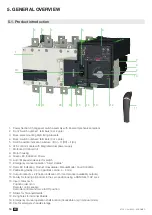
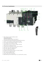
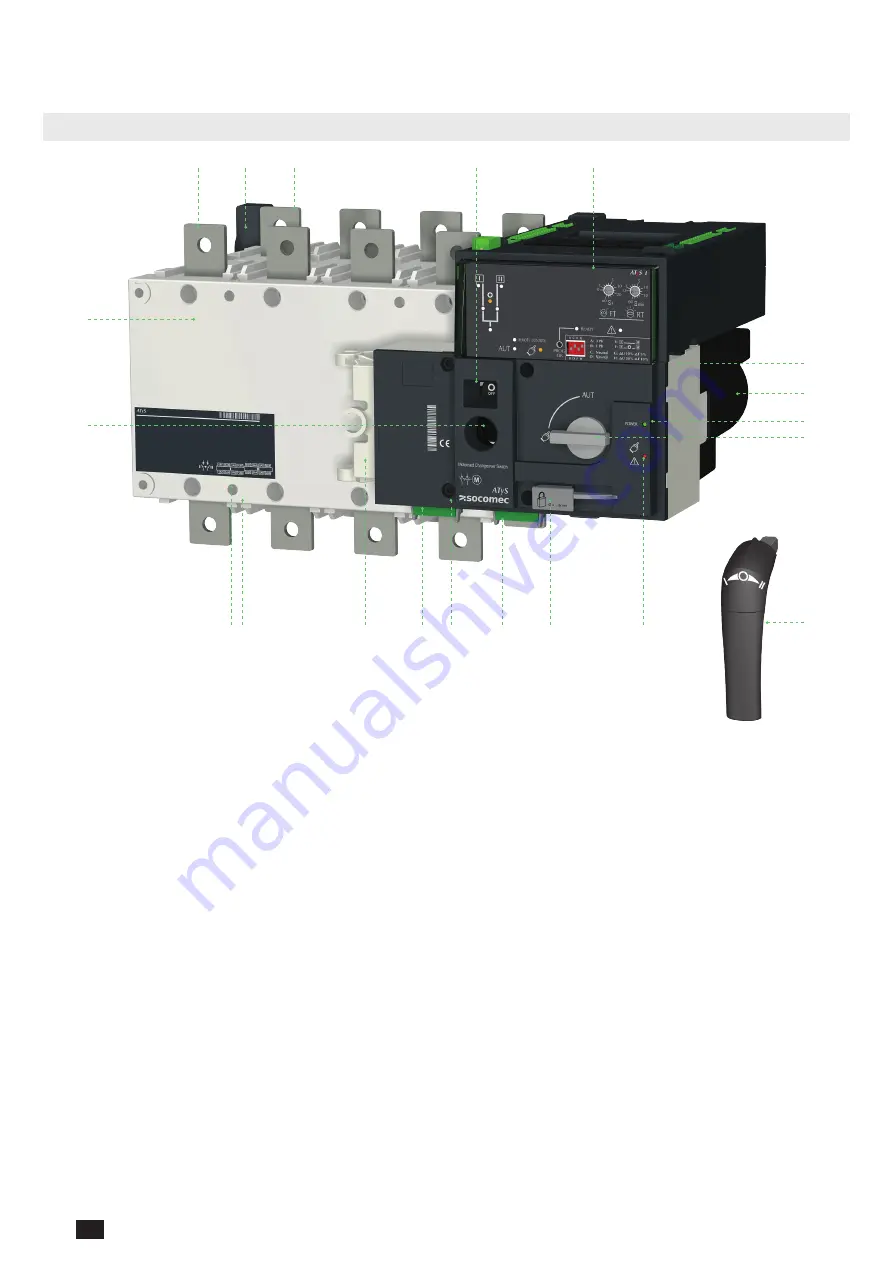
5. GENERAL OVERVIEW
5.1. Product introduction
1
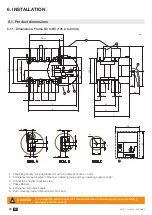
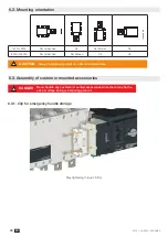
7
8
9
10
12
13
14
15
16
20
16 17
19
2
3
4
5
6
11
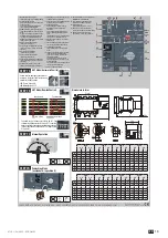
1.
Power Section: Changeover switch assembly with inherent mechanical interlock
2.
Front: Switch number 1 terminals (3 or 4 pole)
3.
Back-plate mounting ATyS fixing brackets
4.
Back: Switch number 2 terminals (3 or 4 pole)
5.
Switch position indication window: I (On) – O (Off) – II (On)
6. ATS control module with integrated dual power supply
7. Motorized Control Unit
8. Motor housing
9.
Green LED Indication: Power
10. Auto / Manual mode selector switch
11.
Emergency manual operation “Direct Handle”
12.
Red LED Indication: Product Unavailable / Manual Mode / Fault Condition
13.
Padlocking facility (Up to 3 padlocks of dia. 4 – 8mm)
14.
Output contacts x 4 (Position indication I-O-II and product availability outputs)
15.
Facility for locking all controls in the zero position using a RONIS EL11AP Lock
16.
Input contacts x 5:
Position order I-O-II
Remote control enable
Override controls and force to Off position
17. Sliders for Terminal Shields
18.
Fixing holes for terminal Shields
19.
Emergency manual operation shaft location (Accessible only in manual mode)
20. Clip for emergency handle storage
Summary of Contents for ATyS g
Page 5: ...5 EN ATYS t 541995C SOCOMEC ...
Page 25: ...25 EN ATYS t 541995C SOCOMEC ...


