background image

24

EN

ATYS t - 541995C - SOCOMEC
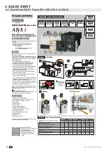
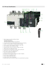
5.5. ATy

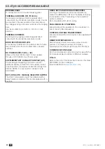
S t ACCESSORIES AVAILABLE
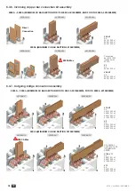
BRIDGING BARS

To connect switch I & II load terminals together. 

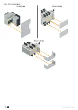
TERMINAL SHROUDS (125 TO 630 A)

Incoming and outgoing protection against direct 
contact with the connection terminals or parts. Cannot 
be mounted in the rear position at the same time as 
the voltage sensing and power outlet kit or the bridging 
bars.
Can be mounted top or bottom, in front or in rear 
position.

TERMINAL SCREENS

Incoming and outgoing protection against direct 
contact with the connection terminals or parts.

DOOR ESCUTCHEON PLATE

An accessory to be fixed onto a cabinet door to frame 
the controller part of flush mounted AT

y

S p transfer 

switches. 

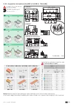
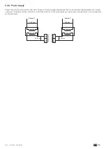
DC POWER SUPPLY (DC -> AC)

Allows a standard 230Vac ATyS t to be supplied 
through a 12/24/48Vdc Aux Power supply.

SUPPLEMENTARY AUXILIARY CONTACT (AC)

Pre-breaking and signaling of positions I and II: 1 
additional auxiliary contact NO / NC auxiliary contact 

in each position. Included as standard for ratings from 

2000 to 3200A. For Low level AC: please consult 

SOCOMEC. 

KEY LOCK AUTO / MANUAL SELECTOR SWITCH

The ATy

S t mode selector switch is delivered with a 

rotary handle as standard. This can be replaced with a 
key lock.

RONIS KEY PADLOCKING ACCESSORIES

Locking of the electrical and manual operation by 
means of a RONIS EL11AP lock. Possibility of locking 
in all positions, if the “Padlocking in the 3 positions” 

option is ordered.

Not compatible with flush mounting.

PADLOCKING IN 3 POSITIONS

Allows locking of the operation in the 3 positions I, 0 

and II. (Factory fitted accessory) 

CONTROL VOLTAGE TRANSFORMER

Allows a standard 230 V AC device to be supplied with 

400 VAC.

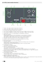
REMOTE INTERFACES D10


Remote Display: Allows source supply state and switch 
positions to be displayed remotely. (LED display)

Typically door mounted or ≤3m away from the AT

yS.

COMMUNICATION CABLE

RJ 45 communication cable (3m long) for use with the 
D1

0 remote display/controller or Ethernet modules.

Others:

Refer to the end of this instruction manual or the latest 
SOCOMEC product catalogue. 

(Downloadable from 

www.socomec.com

)

Summary of Contents for ATyS g

Page 1: ...Automatic Transfer Switching Equipment ATyS t www socomec com en documentation atys t INSTRUCTION MANUAL EN ...

Page 2: ...URE 21 5 4 3 2 STORAGE DURATION PERIOD 22 5 4 3 3 STORAGE POSITION 22 5 4 4 VOLUME AND SHIPPING WEIGHTS BY REFERENCE ATYS T 22 5 4 5 CE MARKING 23 5 4 6 LEAD FREE PROCESS 23 5 4 7 WEEE 23 5 4 8 EMC STANDARD 23 5 5 ATYS T ACCESSORIES AVAILABLE 24 6 INSTALLATION 26 6 1 PRODUCT DIMENSIONS 26 6 1 1 DIMENSIONS FRAME B3 TO B5 125 A TO 630 A 26 6 1 2 DIMENSIONS FRAME B6 B7 800 A TO 1600 A 28 6 1 3 DIMENS...

Page 3: ...TWORK 47 8 ATYS T OPERATING MODES AND SEQUENCES 48 8 1 MANUAL OPERATION 49 8 1 1 EMERGENCY MANUAL OPERATION 49 8 1 2 PADLOCKING 49 8 2 ELECTRICAL OPERATION 50 8 2 1 DUAL POWER SUPPLY 50 8 2 2 VOLTAGE SENSING INPUTS 50 8 2 3 FIXED INPUTS 51 8 2 3 1 DESCRIPTION 51 8 2 3 2 TECHNICAL DATA 52 8 2 3 3 REMOTE CONTROL LOGIC 53 8 2 4 FIXED OUTPUTS DRY CONTACTS 54 8 2 4 1 DESCRIPTION 54 8 2 4 2 POSITION AUX...

Page 4: ...PPLY KIT 65 13 10 VOLTAGE RELAY 65 13 11 DOOR PROTECTIVE SURROUND 66 13 12 AUXILIARY CONTACTS ADDITIONAL 66 13 13 3 POSITION PADLOCKING I 0 II 66 13 14 RONIS KEY INTERLOCKING SYSTEM 66 13 15 REMOTE INTERFACE 67 13 16 CONNECTION CABLE FOR REMOTE INTERFACE 67 13 17 SEALABLE COVER 67 13 18 AUTO MANUAL KEY SELECTOR 67 14 SPARE PARTS 68 14 1 ELECTRONIC MODULE 68 14 2 MOTORISATION MODULE 68 14 3 POWER S...

Page 5: ...5 EN ATYS t 541995C SOCOMEC ...

Page 6: ... injury and or damage to equipment This instruction manual must be made accessible so as to be easily available to anyone who may need to read it in relation with the ATyS t The ATyS t meets the European Directives governing this type of product and includes CE marking on each product No covers on the ATyS t should be opened with or without voltage as there may still be dangerous voltages inside t...

Page 7: ...ve HMI for emergency local operation Integrated and robust switch disconnection Window with clearly visible position indication I 0 II An inherent failsafe mechanical interlock Stable positions I 0 II non affected by typical vibration and shocks Constant pressure on the contacts non effected by network voltage Energy Efficient with virtually no consumption whilst on the normal alternate or off pos...

Page 8: ...d on the application as well as the nature of installation in which the ATyS will be installed This instruction manual includes details and instructions specific to the ATyS t ATSE only For all other ATyS family of products please refer to the specific instruction manual related to that product Available for download on www socomec com An overview of the complete ATyS range is presented below The ...

Page 9: ...9 2 11 3 5 2 Programmable I O 6 1 Additional programmable I O modules Optional up to 4 modules 8 8 Remotely operated Transfer Switching Equipment RTSE Class PC Automatic Transfer Switching Equipment ATSE Class PC Remote Manual Control Auto Remote Manual Control Auto Remote Local Manual Control Auto configuration of voltage and frequency levels Switch Position LED display Security Sealing Cover Con...

Page 10: ...all in the cabinet risk of electrical arcing For 125 160 A Uimp 8 kV Terminations must respect a minimum of 8 mm clearance from live parts to parts intended to be earthed and between poles For 200 630A Uimp 12 kV Terminations must respect a minimum of 14 mm clearance from live parts to parts intended to be earthed and between poles Failure to observe good enginering practises as well as to follow ...

Page 11: ...Sensing and Control wiring ATS Controller ATS Module Control Inputs Fixed ATS Module Output Contact Product available Remote interface RJ45 to ATyS D10 ATS Voltage Sensing Input Source supply I S I Phase Neutral S I Phase S I Phase 575 VAC ph ph max S I Neutral Phase 332 VAC ph n max ATS Power Supply Input I Power supply I L N Power supply I N L 208 277 VAC 20 50 60 Hz Recommanded to use SOCOMEC V...

Page 12: ...e changed and until the new settings have been saved by pressing the PROG OK button momentarily The ATyS t includes an Auto Configuration feature to detect the mains voltage and frequency nominal values phase rotation and neutral position and saves them in the ATS controller Note Before configuring the nominal values ensure that the product is properly wired verified and ready for commissioning It...

Page 13: ... 51 13 0 51 13 X 1 30 33 1 30 33 1 30 33 1 30 33 1 67 42 5 1 48 37 5 1 67 42 5 1 48 37 5 3x Ø4 8 mm 19 20 21 22 5 4 2 1 3 13 17 18 14 15 12 16 8 9 6 7 10 11 W U CA 5 43 138 6 50 165 X T Fix M F C Fix 7 38 187 5 0 83 21 9 04 229 5 0 49 12 5 0 30 7 5 0 34 8 6 0 64 16 2 0 64 16 2 0 34 8 6 1 MANUAL Mode LED indication Yellow steady light when in Manual Mode 2 AUTO Mode LED indication Green steady ligh...

Page 14: ...thed and between poles Failure to observe good enginering practises as well as to follow these safety instructions may expose the user and others to serious injury or death Risk of damaging the device In case the product is dropped or damaged in any way it is recommended to replace the complete product Accessories Bridging bars and connection kits Control voltage transformer 400 VAC 230 VAC DC pow...

Page 15: ...Supply Sensing and Control wiring ATS Controller ATS Module Control Inputs Fixed ATS Module Output Contact Product available Remote interface RJ45 to ATyS D10 ATS Voltage Sensing Input Source supply I S I Phase Neutral S I Phase S I Phase 575 VAC ph ph max S I Neutral Phase 332 VAC ph n max ATS Power Supply Input I Power supply I L N Power supply I N L 208 277 VAC 20 50 60 Hz Recommanded to use SO...

Page 16: ...e changed and until the new settings have been saved by pressing the PROG OK button momentarily The ATyS t includes an Auto Configuration feature to detect the mains voltage and frequency nominal values phase rotation and neutral position and saves them in the ATS controller Note Before configuring the nominal values ensure that the product is properly wired verified and ready for commissioning It...

Page 17: ... 45 0 98 25 0 98 25 1 30 33 0 39 10 800 A 1000 A 2000 A 3200 A 800 A 1600 A 1250 A 1600 A 3200 A CORPORATE HQ CONTACT SOCOMEC SAS 1 4 RUE DE WESTHOUSE 67235 BENFELD FRANCE WWW SOCOMEC COM 1 MANUAL Mode LED indication Yellow steady light when in Manual Mode 2 AUTO Mode LED indication Green steady light when in Auto mode with no timers running Green flashing light when in Auto with timers running in...

Page 18: ...Green LED Indication Power 10 Auto Manual mode selector switch 11 Emergency manual operation Direct Handle 12 Red LED Indication Product Unavailable Manual Mode Fault Condition 13 Padlocking facility Up to 3 padlocks of dia 4 8mm 14 Output contacts x 4 Position indication I O II and product availability outputs 15 Facility for locking all controls in the zero position using a RONIS EL11AP Lock 16 ...

Page 19: ...ference number label 5 ATS controller contact identification labels 6 Network status and switch position pictogram with LED s 7 Mains failure timer setting dial 0 60s 8 ATyS product type identification ATyS t ATyS g or ATyS p 9 Mains return timer setting dial 0 60mins 10 Dip switch configuration identification 11 Motor barcode and serial number 12 Emergency manual operation direction of rotation i...

Page 20: ...URN Time RT Potentiometer to set the supply adjustable from 0 to 60min 10 Sealing screw location 2 for use with the sealing cover 11 FAULT LED indication Red steady light in case of an ATS controller internal fault and blinking in case of an external fault rotation incorrect neutral position incorrect Switch the product from Auto to Manual and back to Auto to reset a fault condition 12 Configurati...

Page 21: ...ure From 20 to 40 C without derating From 20 to 70 C when applying a Kt derating correction factor Kt Correction Factor Temperature 0 9 40 C 50 C 0 8 50 C 60 C 0 7 60 C 70 C Simplified derating method Ithu Ith x Kf A more precise calculation may be done for specific applications Should this be required please contact SOCOMEC 5 4 2 2 Hygrometry 80 humidity without condensation at 55 C 95 humidity w...

Page 22: ...3 9543 3025 8 0 11 3 585x385x310 4 9543 4025 8 8 12 1 585x385x310 315 A 3 9543 3031 8 1 11 4 585x385x310 4 9543 4031 9 2 12 5 585x385x310 400 A 3 9543 3040 8 1 11 4 585x385x310 4 9543 4040 9 2 12 5 585x385x310 B5 500 A 3 9543 3050 12 8 16 1 585x385x385 4 9543 4050 14 7 18 0 585x385x385 630 A 3 9543 3063 13 3 16 6 585x385x385 4 9543 4063 15 4 18 7 585x385x385 B6 800 A 3 9543 3080 29 0 45 0 730x800x...

Page 23: ...directive 5 4 8 EMC standard The ATyS t is designed and built in accordance with IEC 60947 1 standards Products intended to be installed in an Industrial Commercial and or Residential Environment therefore respecting both Class A as well as Class B EMC requirements DESCRIPTION STD IEC REQUIREMENT CRITERIA Conducted CISPR 11 Class B Radiated CISPR 11 Class B ESD contact 61000 4 2 4KV B ESD air 6100...

Page 24: ...t in each position Included as standard for ratings from 2000 to 3200A For Low level AC please consult SOCOMEC KEY LOCK AUTO MANUAL SELECTOR SWITCH The ATyS t mode selector switch is delivered with a rotary handle as standard This can be replaced with a key lock RONIS KEY PADLOCKING ACCESSORIES Locking of the electrical and manual operation by means of a RONIS EL11AP lock Possibility of locking in...

Page 25: ...25 EN ATYS t 541995C SOCOMEC ...

Page 26: ...2 16 2 8 6 W U CA 138 165 1 Padlocking Facility Locking bracket for up to 3 padlocks of dia 4 8mm 2 Emergency manual operation Maximum operating radius with an operating angle of 2x 90 3 Connection and disconnection area 4 Phase Barriers 5 Emergency removable handle 6 Flush mounting cutout dimensions for front door CAUTION To consider the space required for manual operation and wiring when using t...

Page 27: ... 317 328 378 328 378 328 378 377 437 377 437 H 151 151 151 151 151 151 152 152 152 152 152 152 221 221 221 221 J 154 184 154 184 154 184 195 245 195 245 195 245 244 304 244 304 J1 34 34 34 34 34 34 35 35 35 35 35 35 34 34 34 34 M 120 150 120 150 120 150 160 150 160 210 160 210 210 270 210 270 T 36 36 36 36 36 36 50 50 50 50 50 50 65 65 65 65 U 20 20 20 20 20 20 25 25 35 35 35 35 32 32 45 45 V 25 2...

Page 28: ...nnection and disconnection area 4 Terminal screens 5 Phase Barriers 6 Emergency removable handle 7 Flush mounting cutout dimensions for front door 800 A 1000 A 1250 A 1600 A 3P 4P 3P 4P 3P 4P 3P 4P AA 321 321 321 321 330 330 288 288 AC 461 461 461 461 461 461 531 531 B 370 370 370 370 370 370 380 380 F 504 584 504 584 504 584 596 716 J 307 387 307 387 307 387 399 519 M 255 335 255 335 255 335 347 ...

Page 29: ...cility Locking bracket for up to 3 padlocks of dia 4 8mm 2 Emergency manual operation Maximum operating radius with an operating angle of 2x 90 3 Connection and disconnection area 4 Terminal screens 5 Phase Barriers 6 Emergency removable handle 7 Flush mounting cutout dimensions for front door 2000 A 3200 A 3P 4P 3P 4P F 596 716 596 716 J 398 5 518 5 398 5 518 5 M 347 467 347 467 CAUTION To consid...

Page 30: ...ended Not Allowed OK OK CAUTION Always install the product on a flat and rigid surface 6 3 Assembly of customer mounted accessories DANGER Never handle any customer mounted accessories while there may be the risk of voltage being or becoming present 6 3 1 Clip for emergency handle storage Max tightening torque 2 5 Nm ...

Page 31: ...the switch Recommended tightening torque M6 4 5 N m M8 8 3 N m M10 20 N m M12 40 N m Maximum tightening torque M6 5 4 N m M8 13 N m M10 26 N m M12 45 N m 6 3 3 Terminal shrouds Available from 125 A to 630 A Frame B3 to Frame B5 Upstream downstream front or rear mounting When fitted with bridging bars only the front terminal shrouds are to be installed ...

Page 32: ...32 EN ATYS t 541995C SOCOMEC 6 3 4 Terminal screens 125 A to 630 A 500 A to 1600 A 2000 A to 3200 A ...

Page 33: ...act MOY M M12 NFE 25 511 H M12 01 H M12 35 6 8 6 x 12 x 6 x 02 H M12 55 6 8 3 x 6 x 3 x 03 H M12 55 6 8 5 x 10 x 5 x 04 H M12 35 6 8 3 x 3 x H M12 45 6 8 3 x 3 x 05 H M12 65 6 8 3 x 6 x 3 x 06 H M12 65 6 8 5 x 10 x 5 x 07 H M12 55 6 8 3 x 6 x 3 x 08 H M12 55 6 8 5 x 10 x 5 x 09 H M12 55 6 8 10 x 20 x 10 x 10 H M12 65 6 8 3 x 6 x 3 x 11 H M12 65 6 8 5 x 10 x 5 x 12 H M12 65 6 8 10 x 20 x 10 x A B C...

Page 34: ...19 1200 included with 3200 A V4 Kit 2699 1200 x 1 V5 V6 Kit 2629 1200 x 1 2639 1200 x 1 6 3 7 Outgoing bridge connection assembly 2000 A 2500 A MINIMUM CU BAR SECTION FOR ITH 2000 A 3X100X5MM FOR ITH 2500 A 4X100X5MM VERSION 07 VERSION 08 VERSION 09 V7 V8 Kit 2619 1200 x 2 2699 1201 x 2 2629 1200 x 1 4109 0320 x 1 V9 Kit 2619 1200 x 2 2629 1200 x 2 2639 1200 x 2 3200 A MINIMUM CU BAR SECTION 3X100...

Page 35: ...se voltage applications that do not provide the availability of a neutral conductor Transformer data 400 VAC 230 VAC 200 VA In this case the ATyS t will require 2 transformers to be connected as shown below 101 Power 230 Vac Power 230 Vac 400 Vac 230 Vac 102 Source 1 202 400 Vac 230 Vac 201 Source 2 ...

Page 36: ... 3 10 Additional auxiliary contacts Intended for pre breaking and signaling of positions I and II A maximum of 2 NO NC additional auxiliary contacts can be fitted for each position Customer assembly may be required 82 92 84 94 81 91 fast on Pos II Pos I 81 81 82 84 91 92 94 Pos I Pos II 82 84 91 92 94 2x 1 125 A to 630 A Optional 800 A to 1600 A Optional 2000 A to 3200 A Standard 1 When mounting o...

Page 37: ... CAUTION For B3 8kV Terminations must respect a minimum of 8 mm clearance from live parts to parts intended to be earthed and between poles For B4 5 6 7 8 12kV Terminations must respect a minimum of 14 mm clearance from live parts to parts intended to be earthed and between poles 7 1 2 Power connection terminals 125 A TO 630 A REFER TO SECTION PRODUCT DIMENSIONS PAGE 26 FOR POWER CONNECTION TERMIN...

Page 38: ...0 185 2x95 2x120 2x185 Recommended cable section Cu mm Ith 2x32 x5 2x40 x5 2x50 x5 2x63 x5 2x60 x7 2x100 x5 3x100 x5 2x100 x10 3x100 x10 Maximum cables section Cu mm2 50 95 120 150 240 240 2x185 2x300 2x300 4x185 4x185 6x185 Maximum bars width Cu mm 25 25 25 32 32 32 50 50 63 63 63 100 100 100 100 Note for all ratings Take into account the connection cable lengths and or others environmental speci...

Page 39: ...60Hz on 22VA ion sheet ATyS g Aux Supply 2 Power 208 277 Vac 20 166 332Vac 50 60 Hz L N 201 N L 202 Aux Supply 1 Power 208 277 Vac 20 166 332Vac 50 60 Hz 101 L N 102 N L To D10 To D20 64B 63B 64B 63B 417 416 415 414 413 207 208 209 210 417 416 415 414 413 207 208 209 210 71 72 74 71 72 74 Dual auxiliary supply Uc 208 277V 20 50 60Hz Power comsumption 22VA See instruction sheet ATS CONTROLLER ATyS ...

Page 40: ...Three phase network without neutral with 1 CT connected on Phase 1 3NBL Three phase network without neutral 1 Source 1 Load Source 2 2 3 1 2 3 1 Source 1 Load Source 2 2 3 1 2 3 4BL Three phase network with neutral with 1 CT connected on Phase 1 4NBL Three phase network with neutral 1 Source 1 Load Source 2 2 3 N 1 2 3 N 1 Source 1 Load Source 2 2 3 N 1 2 3 N ...

Page 41: ... 3 2 1 3 2 1 3 2 N 1 3 2 N ATyS p CT cabling load side 1 N R1 R2 1 3 2 R2 R1 1 3 2 R2 S1 T1 T2 S2 R1 1 R1 R2 3 2 N 1 R1 S2 T2 T1 S1 R2 3 2 N VOLTAGE SENSING Source 1 V1 U12 U23 U31 U12 U23 U31 U12 U23 U31 V1 V2 V3 U12 U23 U31 V1 V2 V3 Source 2 V1 U12 U23 U31 U12 U23 U31 U12 U23 U31 V1 V2 V3 U12 U23 U31 V1 V2 V3 Source presence source available Source in ranges U V F Rotation phase order Neutral po...

Page 42: ...2 Position I order 3 Position II order 4 Zero position priority order 5 Remote Control Enable Priority over Auto 6 Product Available output Motor 7 Position II aux contact 8 Position I aux contact 9 Position 0 aux contact 10 O P to D10 remote display 11 Product Available output ATS 12 I P Inhibition of the ATS controls 13 I P Manual retransfer RTC 14 I P to define the source priority Source priori...

Page 43: ...OLLER To D10 To D20 64B 63B 64B 63B 417 416 415 414 413 207 208 209 210 417 416 415 414 413 207 208 209 210 71 72 74 71 72 74 ATyS t Dual auxiliary supply Uc 208 277V 20 50 60Hz Power comsumption 22VA See instruction sheet ATS CONTROLLER ATyS p Dual auxiliary supply Uc 208 277V 20 50 60Hz Power comsumption 22VA See instruction sheet ATS CONTROLLER ATyS g To D10 To D20 64B 63B 64B 63B 417 416 415 4...

Page 44: ...r 2 of Switch I ATS POWER SUPPLY INPUT II 201 L N Power supply II L N 208 277Vac 20 50 60Hz 1 5 2 5 mm2 202 N L Power supply II N L ATS VOLTAGE SENSING INPUT SWITCH II 203 1 2 Phase or neutral connected on power contact 1 or 2 of Switch II 575 Vac ph ph max 332Vac ph n max 1 5 2 5 mm2 204 3 4 Phase connected on power contact 3 or 4 of Switch II 205 5 6 Phase connected on power contact 5 or 6 of Sw...

Page 45: ...bles connections Tighten the cables carefully 7 4 1 Standard configuration The sensing and power supply kit may be ordered in 3 phases network 4 wires or 3 wires It can be used with top or bottom cables entry The only connection to respect is that measures of the source on Switch I must be connected to the inputs located on the right of the electronic module and the measures of the source on Switc...

Page 46: ...s Switch I Example Black and red wire numbers 1 2 are always connected to terminals 1 or 2 from switch I or II II 1 3 5 7 2 4 6 8 erminals kit 4 poles onnection on power supply and control module 800 A 102 101 106 105 104 103 I 1 3 5 7 2 4 6 8 7 8 5 6 3 4 1 2 wires Black wires 1 2 6 7 8 6 7 8 1 2 3 4 5 6 7 8 1 2 3 4 5 6 7 8 A B A B mechanical cables support 202201 04 203 CAUTION Verify kit orienta...

Page 47: ... the network configuration Power supply to be taken between phase to phase or between phase and neutral CAUTION Verify that the power supply between terminals 101 102 and 201 202 nominal auxiliary voltage supply is within 208 277 VAC 20 Standard kit Network 380 415 VAC 20 with neutral conductor no kit modification required Kit Modification For network 220 240 VAC 20 power supply cables A B to conn...

Page 48: ...n in AUT Mode AUTO Mode position is inhibited when padlocked or when the handle for manual operation is inserted into the ATyS t MODE 90 90 I II 0 AUT MANUAL MODE Not Padlocked Inhibits the control inputs Allows to insert the handle for emergency manual operation Allows padlocking in O Position With the handle for manual operation removed Turning the selector switch to from AUT and back to AUT res...

Page 49: ...product position and direction of rotation before effecting manual operation Ensure to remove the handle from the product before changing the selector switch back to AUT position 8 1 2 Padlocking The ATyS t can be padlocked in the 0 position as standard whilst padlocking in positions I O or II is available as a factory fitted option To padlock the ATyS t first ensure that the ATyS t mode selector ...

Page 50: ...ally tapped directly off the ATyS t power terminals using the ATyS sensing kit available as an accessory Sensing kits are available with the neutral on the left or neutral on the right to match the network configuration where the ATyS will be operating Refer to the ATyS accessory section for more details Sensing values measured will have a direct influence on determining the availability of the ma...

Page 51: ...313 Position 0 order if closed with 317 when in AUTO Force the switch to the OFF Position This is a Priority Order Input meaning that when closed with 317 it takes priority over all other electrical commands The ATyS t will remain in 0 position as long as the contact 313 317 remains closed Once the contact is open the ATyS t is ready to receive new orders This contact order is independent of other...

Page 52: ... manual mode with the direct handle or in remote control mode with contacts 312 317 closed Pin 417 Common Common supply for fixed inputs 1 4 on terminals 413 to 416 8 2 3 2 Technical data MOTORISATION MODULE ATS CONTROL MODULE Input Qty 5 6 Direct Current Iin 0 35 to 0 5mA 1 to 2 5mA Line resistance 1kΩ 1kΩ Line length 100m Min wire 1 5mm 16AWG 100m Min wire 1 5mm 16AWG Pulse duration 60ms 60ms Po...

Page 53: ...hing command of at least 60 ms is necessary to initiate the switching operation Orders I and II have priority over order 0 Note The logic diagrams exclude the transfer times Imp 60ms order I position I order 0 position 0 order II position II Impulse logic Note Excludes position switching delays Contactor Logic The ATyS t is driven to a specific position I or II for as long as the order is maintain...

Page 54: ...switched from AUT Manual Auto mode ATyS t Motorisation Product Available Unavailable Watchdog relay will open for any of the following reasons below For added security Product Availability is informative and does not necessarily inhibit motor operation Product Unavailable Warning LED Condition Inhibition Product in manual mode Yes Motor not detected Autotest No Control voltage out of range Yes Ope...

Page 55: ...ct opening time I 0 or II 0 POT This time is measured from the instant that the monitored supply is not considered as available to the opening of the main contacts exclusive of any purposely introduced time delay If the product is controlled via external orders this time is measured from the moment when the order is received to the opening of the main contacts 3 Contact transfer time CTT IEC 60947...

Page 56: ... voltage and frequency Press the PROG OK button for 2 seconds to read the network values STEP 4 SAVE all the configured setting values Potentiometers Dipswitches and Auto Conf Press the PROG OK button momentarily to save 60ms Note The READY LED will stop flashing OFF STEP 5 To put the unit in service Switch the ATyS t to AUT mode after STEP 4 Note The READY LED should turn to a Steady Green light ...

Page 57: ...1 12 13 14 3 3 4 4 5 5 6 6 7 7 8 8 9 10 N ΔU ΔF XXX XXXXXXXX Set Pot PROG Press 60ms Press 2s y PROG Set Dip 2 3 4 5 OG DIP SWITCH SETTING OPTIONS Dipswitch 1 A B A Three Phase Network B Single Phase Network Attn Dipswitch 2 is inactive in this position Dipswitch 2 C D C Three Phase 4 wire Network Including Neutral Allows to detect a loss of neutral for unbalanced loads D Three Phase 3 wire Networ...

Page 58: ...D will flash green on and off as soon as settings are measured and until these settings have been saved by pressing the PROG OK button a second time momentarily Refer to STEP 4 9 3 4 Step 4 Saving the configured values To SAVE the recorded setting configuration press the PROG OK button momentarily 60ms Note The flashing READY LED goes off once the values are saved in the ATS controller POWER AUT Ø...

Page 59: ...nditional short circuit with fuse gG DIN according to IEC 60947 3 Prospective fuse protected short circuit withstand at 415 VAC 6 100 100 50 50 50 50 50 50 Prospective fuse protected short circuit withstand at 690 VAC kA rms 50 50 50 50 50 Associated fuse rating A 125 160 200 250 315 400 500 630 Short circuit withstand without protection as per IEC 60947 3 Rated short time withstand current 0 3s I...

Page 60: ...spective fuse protected short circuit withstand at 690 VAC kA rms 50 50 50 Associated fuse rating A 800 1000 1250 2x800 Short circuit withstand without protection as per IEC 60947 3 Rated short time withstand current 0 3s Icw at 415 VAC kA rms 64 64 64 78 78 78 78 Rated short time withstand current 1s Icw at 415 VAC kA rms 35 35 35 50 50 50 50 Rated peak withstand current at 415 VAC kA peak 55 55 ...

Page 61: ...Note Maintenance should be planned carefully and carried out by qualified and authorised personnel Consideration of the critical level and application where the product is installed should form an essential and integral part of the maintenance plan Good engineering practice is imperative whilst all necessary precautions must be taken to ensure that the intervention whether directly or indirectly r...

Page 62: ...peration is not inserted into the ATyS manual slot Verify that the ATyS is in 0 position Padlocking is only possible in 0 position for standard products The ready light remains flashing The Ready light flashes so as to indicate that the saved configuration is not identical to what is displayed on the ATS controller This could be due to a user not yet having saved the configuration settings or that...

Page 63: ...e Top and bottom protection against direct contact with terminals or connection parts For upstream and downstream protection order the reference once Rating A Frame size No of poles Position Reference 125 200 B3 3 P top bottom 1509 3012 125 200 B3 4 P top bottom 1509 4012 250 400 B4 3 P top bottom 1509 3025 250 400 B4 4 P top bottom 1509 4025 500 630 B5 3 P top bottom 1509 3063 500 630 B5 4 P top ...

Page 64: ...ridged from factory Bolt sets must be ordered separately Further details for these specific accessories are available in the user guide downloadable from www socomec com The numbers given in the table below refer to the contact connection Part number 2000 2500 A 3200 A Fig 1 Fig 2 Fig 3 Fig 1 Fig 2 Fig 3 Connection Outage bridge I and II Connection Outage bridge I and II Flat Onsite Flat Onsite Co...

Page 65: ... 13 9 Voltage sensing and power supply kit From 125 to 630 A From 800 to 3200 A For ATyS t g and p 3 poles Rating A Frame size Reference 125 200 B3 1559 3012 250 B4 1559 3025 315 400 B4 1559 3040 500 630 B5 1559 3063 800 1000 B6 1559 3080 1250 B6 1559 3120 1600 B7 1559 3160 2000 3200 B8 1559 3200 For ATyS t g and p 4 poles Rating A Frame size Reference 125 200 B3 1559 4012 250 B4 1559 4025 315 400...

Page 66: ...A Frame size Type of mounting Reference 125 630 B3 B5 Customer fitted 1599 0502 1 800 1600 B6 B7 Customer fitted 1599 0532 1 2000 3200 B8 included 1 Up to 2 auxiliary contacts can be ordered 800 to 1600 A 125 to 630 A Frame size Nominal current A Operating current Ie A Rating A 250 VAC AC 13 400 VAC AC 13 24 VDC DC 13 48 VDC DC 13 125 3200 B3 B8 16 12 8 14 6 13 13 3 position padlocking I 0 II Use ...

Page 67: ...fer switch connection via RJ45 cable not isolated Cable available as an accessory Description of accessories Reference D10 9599 2010 D20 9599 2020 13 16 Connection cable for remote interface acces_209_a_2_cat Use To connect between a remote interface type D10 or D20 and an ATyS transfer switch ATyS d t g or p Characteristics RJ45 8 wire straight through non isolated cable Length 3m For ATyS d t g ...

Page 68: ...with required connectors Rating References 125 200 A 9509 5020 250 400 A 9509 5040 500 630 A 9509 5063 800 1250 A 9509 5120 1600 A 9509 5160 2000 3200 A 9509 5320 14 3 Power section References to be used for replacing the switching module of ATyS r d t g or p Please contact SOCOMEC 14 4 Kit of connectors The kit contains all connectors need to be replaced or missing for ATyS r d t g or p Connector...

Page 69: ...S reference Product 97 UL I O II Type 2 ATYS Ctrl Voltage 3 230 VAC 208 277 VAC Nominal N of poles 2 2 Pole 3 3 Pole 4 4 Pole Rating 010 100 A 020 200 A 026 260 A 040 400 A 97 2 3 4 0 1 0 Note only valid for UL 1008 products Typical IEC 60947 6 1 ATYS reference Product 95 IEC I O II Type 2 ATyS r 3 ATyS d 4 ATyS t 5 ATyS g 7 ATyS p Ctrl Voltage 3 230VAC 166 332VAC N of poles 3 3 Pole 4 4 Pole Rati...

Page 70: ...541995C Non contractual document 2020 Socomec SAS All rights reserved CORPORATE HQ CONTACT SOCOMEC SAS 1 4 RUE DE WESTHOUSE 67235 BENFELD FRANCE www socomec com ...

Reviews: