44
EN
ATYS t - 541995C - SOCOMEC
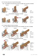
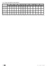
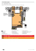
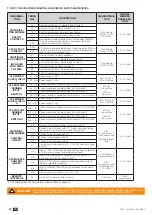
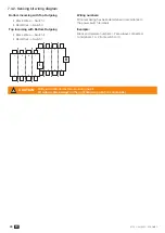
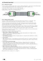
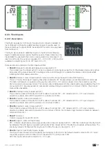
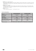
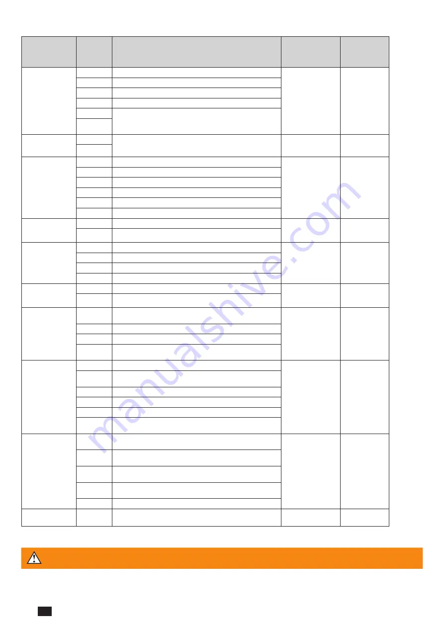
7.3.2.3. Terminal denomination, description and characteristics.
DENOMINA-
TION
TERMI-
NAL
DESCRIPTION
CHARACTERIS-
TICS
RECOM-
MENDED
CABLE SEC-
TION
MOTORISA-
TION MODULE
OUTPUT
CONTACTS
04
Aux Contact Position 0 - Normally Open Contact
Dry Contacts
2A AC1 / 250V
2A / 24Vdc
1.5 – 2.5 mm2
13
Common for Aux Contacts positions I - 0 - II
14
Aux Contact position I: Normally Open Contact
24
Aux Contact position II: Normally Open Contact
63A
Motorisation module available output. Closed when the ATyS t
is in Auto mode and motorisation is operational. (No Fault
powered and ready to changeover)
64A
ATS OUTPUT
CONTACT
63B
ATS control module available output. Closed when the ATyS t is
in Auto mode and ATS is operational. (No Fault, powered and
ready for a changeover sequence)
Dry Contacts
2A AC1 / 250V
1.5 – 2.5 mm2
64B
ADDITIONAL
AUX CONTACT
INCLUDED
WITH 2000A
TO 3200A
81
Common for Aux Contacts positions I
Dry Contacts
2A AC1 / 250V
1.5 – 2.5 mm2
82
Aux Contact position I : Normally Closed Contact
84
Aux Contact position I : Normally Open Contact
91
Common for Aux Contacts positions II
92
Aux Contact position II : Normally Closed Contact
94
Aux Contact position II : Normally Open Contact
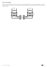
ATS POWER
SUPPLY INPUT
I
101 - L/N
Power supply I – L/N
208 - 277Vac ±
20% : 50/60Hz
1.5 – 2.5 mm2
102 - N/L
Power supply I – N/L
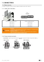
ATS VOLTAGE
SENSING
INPUT*
SWITCH I
103 - 7/8
Phase or neutral connected on power contact 7 or 8 of Switch I
575 Vac
(ph-ph) max
332Vac
(ph-n) max
1.5 – 2.5 mm2
104 - 5/6
Phase connected on power contact 5 or 6 of Switch I
105 - 3/4
Phase connected on power contact 3 or 4 of Switch I
106 - 1/2
Phase or neutral connected on power contact 1 or 2 of Switch I
ATS POWER
SUPPLY INPUT
II
201 - L/N
Power supply II – L/N
208 - 277Vac ±
20% : 50/60Hz
1.5 – 2.5 mm2
202 - N/L
Power supply II – N/L
ATS VOLTAGE
SENSING
INPUT*
SWITCH II
203 - 1/2
Phase or neutral connected on power contact 1 or 2 of Switch
II
575 Vac
(ph-ph) max
332Vac
(ph-n) max
1.5 – 2.5 mm2
204 - 3/4
Phase connected on power contact 3 or 4 of Switch II
205 - 5/6
Phase connected on power contact 5 or 6 of Switch II
206 - 7/8
Phase or neutral connected on power contact 7 or 8 of Switch
II
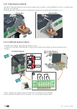
MOTORISA-
TION MODULE
CONTROL
INPUTS
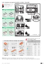
312
Remote Control Mode Enable when closed with 317
Attn:
Do not connect to
any Power supply
Max cable length
100m
1.5 – 2.5 mm2
313
Position 0 order if closed with 317. (Priority order input forcing
the product to remote control mode and 0 position)
314
Position II order if closed with 317
315
Position I order if closed with 317
316
Position 0 order if closed with 317
317
Common control terminal for 312 - 316 ATyS (Specific Voltage
Supply)
ATS MODULE
CONTROL
INPUTS
413
Input I1 : PRI - Activate source supply priority when closed with
417. (Set source priority to network when closed)
Do not connect to
any power supply.
Attn:
To be used with dry
contacts fed from
417 ONLY.
1.5 – 2.5 mm2
414
Input I2: Set priority source supply as SI or SII. (Set as : SI
when open and SII when closed with 417
415
Input I3: RTC – Manual retransfer order when closed with 417.
(Open to validate the retransfer)
416
Input I4: Inhibition of the ATS control automation when closed
with 417
417
Common supply for inputs 1 to 4 (413 - 416)
REMOTE
INTERFACE
RJ
Output to D10 remote display module
Up to 3m
RJ 45
straight cable
*For metering and sensing details, please refer to page 41.
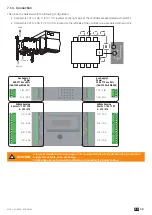
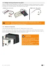
CAUTION
Do not connect terminals 312 to 317, 413 to 417 to any power supply. These order inputs are
powered through terminal 317 (or 417 respectively) and external dry contacts ONLY.
Summary of Contents for ATyS g
Page 5: ...5 EN ATYS t 541995C SOCOMEC ...
Page 25: ...25 EN ATYS t 541995C SOCOMEC ...


