46
EN
ATYS t - 541995C - SOCOMEC
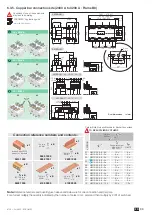
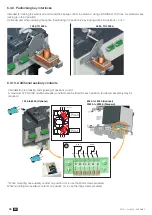
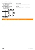
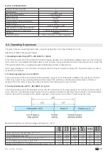
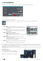
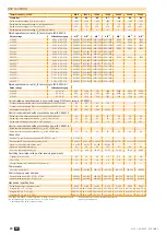
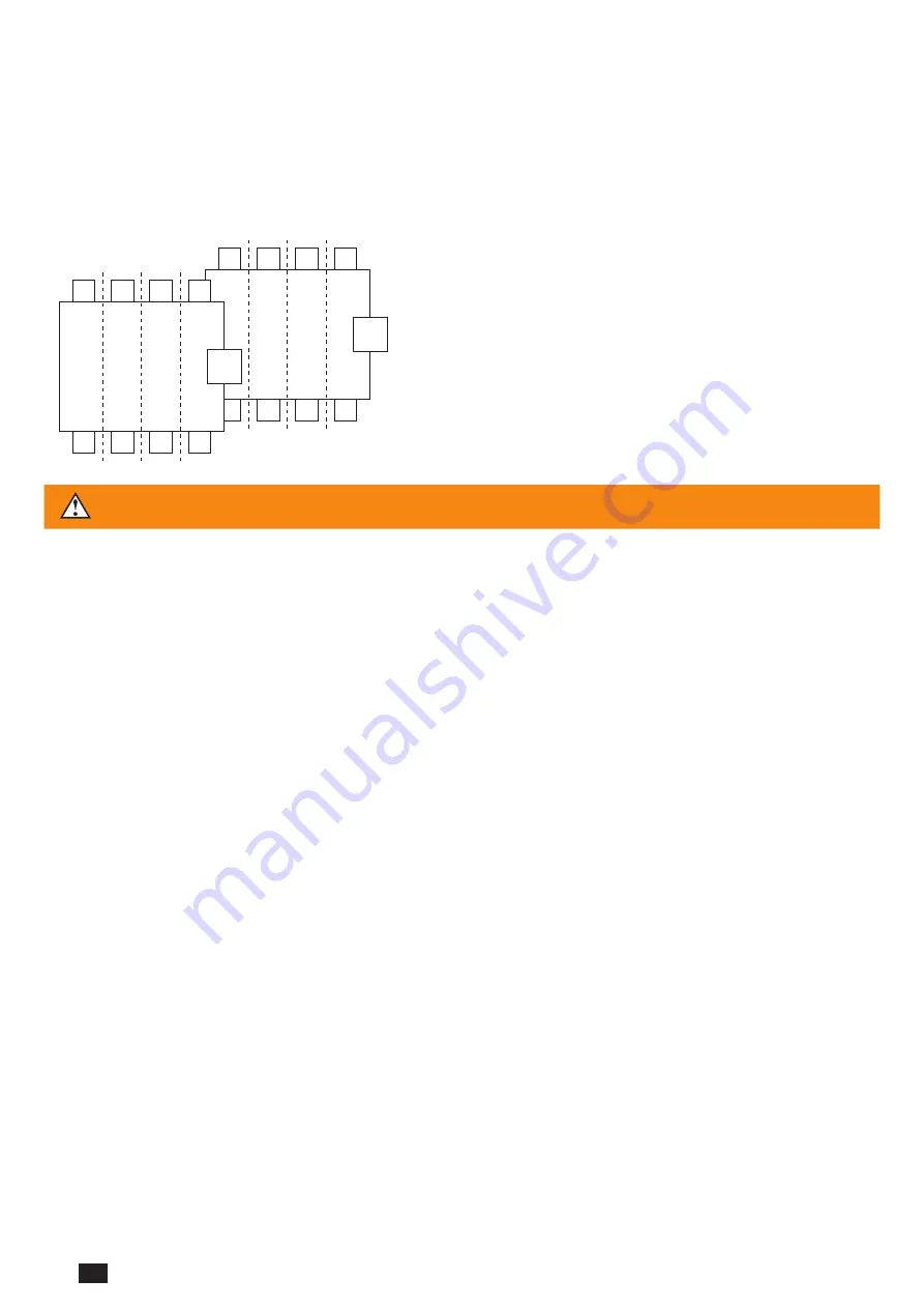
7.4.2. Sensing kit wiring diagram
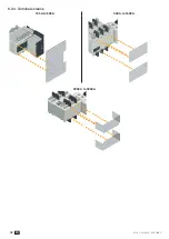
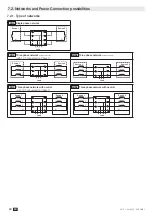
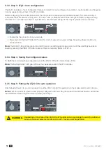
BottomincomingwithTopOutgoing
• Black Wires -> Switch I
• Red Wires -> Switch II
Wiringnumbers:
Wire numbering has been determined in accordance to
the power switch terminals
TopIncomingwithBottomOutgoing
• Black Wires -> Switch II
• Red Wires -> Switch I
Example:
Black and red wire numbers 1-2 are always connected
to terminals 1 or 2 from switch I or II
II
1
3
5
7
2
4
6
8
630 A
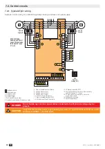
Kit connection on
power switches terminals
Example: 4 wires kit (4 poles)
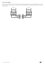
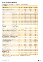
Connection on power supply and control module
800 A
102
101
106
105
104
103
I
1
3
5
7
2
4
6
8
7-8
5-6
3-4
1-2
7-8
5-6
3-4
Red wires
Black wires
1-2
1-2
3-4
5-6
7-8
1-2
3-4
5-6
7-8
1-2
3-4
5-6
7-8
1-2
3-4
5-6
7-8
A
B
A
B
mechanical cables
support
202201
206
205
204
203
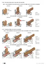
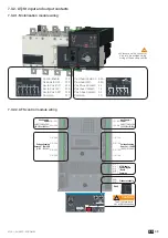
CAUTION
Verify kit orientation before mounting the kit.
Kit output cables always on the right hand side (control module side).
Summary of Contents for ATyS g
Page 5: ...5 EN ATYS t 541995C SOCOMEC ...
Page 25: ...25 EN ATYS t 541995C SOCOMEC ...


