57
EN
ATYS t - 541995C - SOCOMEC
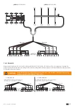
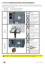
9.3.1.
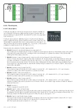
Step 1: ATyS t DIP switches setting options
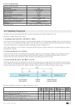
Ensure that the product is in manual mode and SET the 4 Dip Switches using a small screw driver. Possible variants vary from
positions “A to H” as described in the table below. For convenience, the position functions are also described on the front of
the ATS controller adjacent to the dip switches.
Note:
The READY LED will flash green as soon as settings are changed and until the new settings have been saved by
pressing the PROG OK button momentarily.
POWER
AUT
Ø 4 ... 8mm
PROG
OK
AUT
READY
AT
y
S
t
0
1
5
10
20
60
0
1
5
10
20
60
G: U 10% F 5%
H: U 20% F 10%
E:
F:
REMOTE CONTROL
A: 3 Ph
B: 1 Ph
C: Neutral
D: Neutral
Motorised Changeover Switch
AT
y
S
1600A
Ref : 95054160
Un
N°
PP / PN
1:
220 / 127
2:
380 / 220
3:
400 / 230
4:
415 / 240
5:
480 / 277
6:
208 / 120
7:
220 / 127
8:
230 / 132
9:
240 / 138
10:
380 / 220
11:
400 / 230
12:
415 / 240
13:
480 / 277
5
6
7
8
9
10
11
12
13
14
15
16
18
20
1:
2:
3:
4:
5:
6:
7:
8:
9:
10:
11:
12:
13:
14:
3
3
4
4
5
5
6
6
7
7
8
8
9
10
N°:
Δ
U
Δ
F
%
XXX
50 Hz
60 Hz
XXXXXXXX
Set Pot
PROG
AUT
Press
60ms
Press
2s
Ready !
PROG
Set Dip
1
2
3
4
5
PROG
DIP SWITCH SETTING OPTIONS
Dipswitch 1
A / B
A Three Phase Network
B Single Phase Network
(Attn : Dipswitch 2 is inactive in this position)
Dipswitch 2
C / D
C
Three Phase 4 wire Network (Including Neutral)
(Allows to detect a loss of neutral for unbalanced loads)
D Three Phase 3 wire Network (Without Neutral)
Dipswitch 3
E / F
E
Load supply down time of 0 second (0DT = 0 sec)
F
Load supply down time of 2 seconds (0DT = 2 sec)
Dipswitch 4
G / H
G
Threshold Delta U : 10% / Delta F : 5%
H
Threshold Delta U : 20% / Delta F : 10%
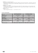
When a transfer is initiated after a loss of source, the 2s time delay is counted down from the loss of source.
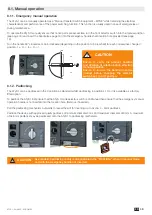
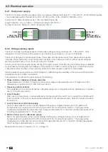
9.3.2.
Step 2: ATyS t potentiometer setting options
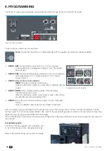
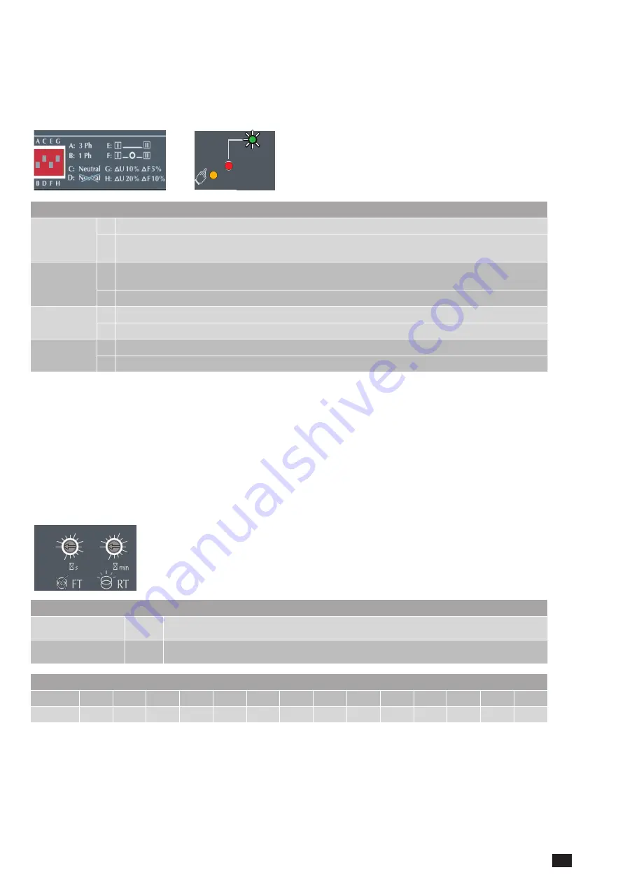
Ensure that the product is in manual mode and SET the 2 potentiometers using a small screw driver paying attention to the
arrow indicating the position. There are a total of 14 time setting positions for which the specific settings are described in the
table below.
Note
: The READY LED will flash green as soon as settings are changed and until the new settings have been saved by
pressing the PROG OK button momentarily.
POWER
AUT
Ø 4 ... 8mm
PROG
OK
AUT
READY
AT
y
S
t
0
1
5
10
20
60
0
1
5
10
20
60
G: U 10% F 5%
H: U 20% F 10%
E:
F:
REMOTE CONTROL
A: 3 Ph
B: 1 Ph
C: Neutral
D: Neutral
Motorised Changeover Switch
AT
y
S
1600A
Ref : 95054160
Un
N°
PP / PN
1:
220 / 127
2:
380 / 220
3:
400 / 230
4:
415 / 240
5:
480 / 277
6:
208 / 120
7:
220 / 127
8:
230 / 132
9:
240 / 138
10:
380 / 220
11:
400 / 230
12:
415 / 240
13:
480 / 277
5
6
7
8
9
10
11
12
13
14
15
16
18
20
1:
2:
3:
4:
5:
6:
7:
8:
9:
10:
11:
12:
13:
14:
3
3
4
4
5
5
6
6
7
7
8
8
9
10
N°:
Δ
U
Δ
F
%
XXX
50 Hz
60 Hz
XXXXXXXX
Set Pot
PROG
AUT
Press
60ms
Press
2s
Ready !
PROG
Set Dip
1
2
3
4
5
PROG
FUNCTIONAL DESCRIPTION
Potentiometer 1
FT
Supply Source Failure time : 0 to 60s
Potentiometer 2
RT
Supply Source Return Time : 0 to 60 min
POSITION SETTING IDENTIFICATION
FT (sec)
0
1
2
3
4
5
8
10
15
20
30
40
50
60
RT (min)
0
1
2
3
4
5
8
10
15
20
30
40
50
60
Summary of Contents for ATyS g
Page 5: ...5 EN ATYS t 541995C SOCOMEC ...
Page 25: ...25 EN ATYS t 541995C SOCOMEC ...

