background image

66

EN

ATyS p M - 542935E - SOCOMEC

13.9.3. Modbus

®

 protocol

The  Modbus

®

  protocol  used  by  the  ATyS  requires  a  dialogue  using  a  master/slave  hierarchical  structure.  Two 

dialogues are possible:

•  the master communicates with a slave (ATyS) and waits for its reply,

•  the master communicates with all the slaves (ATyS) without waiting for their reply.

The mode of communication is the RTU (Remote Terminal Unit) using hexadecimal characters of at least 8 bits.
In the communication protocol, a standard frame is made up of the following elements:

Slave address

Function code

Address

Data

CRC 16

• Slave address: Communicating device address (Add, menu Comm parameters)

• Function code: the codes which can be used are as follows:

  3 :  to read n words (maximum 125)

  6 : to write one word

  16 :  to write n words (maximum 125).

•  Address : Register address (refer to following tables)

•  Data : Parameters linked to function (number of words, value)

When slave address 0 is selected, a message is sent to all devices present on the network (only for functions 6 and 16); 
this type of message is called general distribution, so it is not followed up with a response from the slaves.

The maximum response time (timeout) is 250 ms between a question and a response.

Modbus connector

Summary of Contents for ATyS p M

Page 1: ...ATyS p M Automatic Transfer Switching Equipment EN INSTRUCTION MANUAL www socomec com ...

Page 2: ...socomec com www socomec com catalogues brochures_en To download brochures catalogues and technical manuals This manual is available for download in French English German Italian Spanish Dutch Portugese Russian Polish Turkish and Chinese ...

Page 3: ...IONAL ACCESSORIES 15 6 TECHNICAL DATA 16 7 ENVIRONMENTAL CONDITIONS 17 8 PRODUCT INSTALLATION 18 8 1 CHANGING THE PADLOCKING CONFIGURATION 18 8 2 RECOMMANDED ORIENTATION 18 8 3 DIMENSIONS 18 8 4 BACK PLATE MOUNTED 18 8 5 DIN RAIL MOUNTED 19 9 INSTALLATION OF OPTIONAL ACCESSORIES 20 9 1 AUXILLIARY CONTACTS 20 9 2 VOLTAGE SENSING AND POWER SUPPLY TAP 20 9 3 BRIDGING BARS 4P 20 9 4 TERMINAL SHROUDS 2...

Page 4: ...N 34 13 4 3 DISPLAY PRESENTATION 34 13 4 4 EVENTS 35 13 4 5 EVENTS LIST 35 13 5 PROGRAMMING 37 13 5 1 PROGRAMMING WITH EASYCONFIG 37 13 5 2 PRODUCT PROGRAMMING WITH THE FRONT KEYPAD 37 13 5 3 PROGRAMMING MODE 38 13 5 4 SETUP MENU 40 13 5 5 PHASE ROTATION CHECK 42 13 5 6 VOLT LEVELS MENU 43 13 5 7 OVER VOLTAGE AND UNDER VOLTAGE 44 13 5 8 FREQ LEVELS MENU 45 13 5 9 TIMERS MENU 46 13 5 10 I O MENU 48...

Page 5: ...ES 62 13 7 2 OFF LOAD TEST M G APPLICATION ONLY 62 13 8 EMERGENCY BREAKING TRIP FUNCTION 64 13 9 COMMUNICATION OPTIONAL 9383 XXXX UNITS ONLY 65 13 9 1 COMM MENU 65 13 9 2 GENERAL INFORMATION 65 13 9 3 MODBUS PROTOCOL 66 13 9 4 FUNCTION 3 67 13 9 5 FUNCTION 6 69 13 9 6 FUNCTIONS 3 6 AND 16 70 14 PREVENTATIVE MAINTENANCE 73 15 TROUBLESHOOTING GUIDE 74 ...

Page 6: ...mage to equipment This instruction manual must be made accessible so as to be easily available to anyone who may need to read it in relation with the ATyS The ATyS meets the European Directives governing this type of product and includes CE marking on each product No covers other than that for auto manu on the ATyS should be opened with or without voltage as there may still be dangerous voltages i...

Page 7: ...chanical interlock Stable positions I 0 II non affected by typical vibration and shocks Constant pressure on the contacts non affected by network voltage Energy Efficient with virtually no consumption whilst on the normal alternate or off positions Extremely rugged error free and built in padlocking facility configurable Straight forward installation with effective ergonomics Programmable secure m...

Page 8: ...TRANSITION MOTORISED CHANGEOVER SWITCH DUAL POWER SUPPLY BUILT IN ATS CONTROLLER COMMUNICATION TRIPPING Specific version Return to zero without external energy source A product for virtually all power changeover applications from 40 to 160 A Network Genset Genset Genset Network Network Applications with an External ATS Control Network Genset Network Network ATyS d M GS U P S Network Network Buildi...

Page 9: ...er and micro switch By screen keyboard Vn Fn V threshold F threshold Driving with or without priority Adjustable operating timers Control type impulse or switch contactor DISPLAY Position fully visualised breaking LED source status automatic mode fault LED LED switch positions supply tests control V F timers number of operations last event REMOTE CONTROL Outputs Generator start stop order Product ...

Page 10: ...ROGRAMMING Installation and Commissioning STEP 6A Automatic Operation STEP 6C Padlocking STEP 6B Emergency Manual Operation STEP 3 CONTROL AUX POWER Terminals and wiring Type Terminal no Description Characteristics Recommended connection cross section Inputs 207 Common point for inputs Do not connect to any power supply Supply from the product 0 5 to 2 5 mm rigid 0 5 to 1 5 mm stranded 208 I1 prog...

Page 11: ...STEP 3 STEP 4 Posidriv PZ2 Posidriv PZ2 2 2 lb in 0 25 Nm 2 X Installation Padlocking configuration Caution Ensure that the product is installed on a flat rigid surface MAX 2 340 26 116 53 46 73 5 245 143 350 18 45 13 324 340 326 131 5 131 5 52 104 176 47 Recommended orientation Recommended Ok Ok Ok Ok Ok OK OK OK OK OK OK OK OK OK OK OK OK OK OK OK OK OK OK Posidriv PZ1 1 Nm Tighten to avoid move...

Page 12: ...2 1 2 1 7 1 1 3 3 3 4 4 1 2 4 6 1 2 1 3 2 2 8 1 1 8 1 5 5 5 5 5 1 2 Configure parameters Configure voltage thresholds and hysteresis Frequency thresholds and hysteresis configuration Timer configuration Input output configuration Communication configuration 1 Only accessible if the Setup menu variable APP is at M G see Setup Menu 2 Only accessible if the Setup menu variable APP is at M M see Setup...

Page 13: ...Source 2 return validation timer 0 to 3600 sec 5 sec 2AT Standby network stability validation before transfer 0 to 3600 sec 5 sec 2CT Run on timer 0 to 600 sec 180 sec ODT Dead band timer 0 to 20 sec 3 sec Parameters Setting range Default value NEUTRAL Neutral position on the switch AUTO neutral position is automaticaly detected when the product is supplied the first time LEFT neutral must be conn...

Page 14: ...RS485 communication Modbus for the version with communication CAUTION Ensure that the load is connected to the top of the switch with the motorisation on the right hand side as shown 2 3 7 6 4 5 1 4 2 Specifications and advantages 1 Power section A fully integrated and interlocked transfer switch with high electrical performance offering microprocessor control and monitoring 2 Operation A flexible...

Page 15: ...voltage sensing or power cables The single pole voltage sensing tap can be mounted in the terminals without reducing their connecting capacity Do not use with the bridging bar ATYSM 026 A Ref 1399 4006 2 parts ref Terminal shrouds Protection against direct contacts with terminals or connecting parts Other features Perforations allowing remote thermographic inspection without removal Possibility of...

Page 16: ... fuses Fuse protected short circuit withstand kA eff 50 50 50 50 50 40 Associated fuses gG DIN 40 63 80 100 125 160 Short circuit capacity Rated short term withstand current Icw 1s kA eff 4 4 4 4 4 4 Rated short term withstand current Icw 30ms kA eff 10 10 10 10 10 10 Switching time at In excluding loss of supply sensing time and excluding any delay timers applicable I II or II I ms 180 180 180 18...

Page 17: ...ee Technical Characteristics Altitude Max 2000 m without de rating Correction factors 2 000 m A 3 000 m 3 000 m A 4 000 m UE 0 95 0 80 Ie 0 85 0 85 Storage 1 year maximum Maximum storage temperature 55 C 80 humidity without condensation at 55 C ø 1 mm IP rating IP41 in the SOCOMEC polycarbonate modular enclosure see 10 1 Polycarbonate enclosure page 22 IP2x for non enclosed modular product Protect...

Page 18: ... 0 25 Nm 2 X Posidriv PZ2 OK OK STEP 1 STEP 2 STEP 3 STEP 4 Posidriv PZ2 Posidriv PZ2 2 2 lb in 0 25 Nm 2 X Posidriv PZ2 OK OK STEP 1 STEP 2 STEP 3 STEP 4 Posidriv PZ2 Posidriv PZ2 2 2 lb in 0 25 Nm 2 X Posidriv PZ2 OK OK STEP 1 STEP 2 STEP 3 STEP 4 Posidriv PZ2 Posidriv PZ2 2 2 lb in 0 25 Nm 2 X Posidriv PZ2 OK OK STEP 1 STEP 2 STEP 3 STEP 4 Posidriv PZ2 Posidriv PZ2 2 2 lb in 0 25 Nm 2 X Posidri...

Page 19: ...19 EN ATyS p M 542935E SOCOMEC 8 5 DIN rail mounted errouillage Posidriv PZ1 1 Nm Tighten to avoid movement on the DIN rail DIN RAIL IEC 60715 ...

Page 20: ...use in case of use of the bridging bar Slotted head 3 5 mm 0 45 Nm 0 5 to 2 5 mm 0 5 to 1 5 mm 6 mm 9 3 Bridging bars 4P Ratings 125A ref 1309 4006 160A ref 1309 4016 RJ RS 207208209210 43 44 53 54 63 64 73 74 2 4 6 8 1 3 5 7 2 4 6 8 1 3 5 7 2 4 6 8 1 3 5 7 2 4 6 8 1 3 5 7 RJ RS 207208209210 43 44 53 54 63 64 73 74 2 4 6 8 1 3 5 7 2 4 6 8 1 3 5 7 2 4 6 8 1 3 5 7 2 4 6 8 1 3 5 7 LOAD OK NOK LOAD So...

Page 21: ...21 EN ATyS p M 542935E SOCOMEC 9 4 Terminal shrouds Ref 2294 4016 C K C K ...

Page 22: ...ed size M6 50 mm minimum Weight between 8 and 10 kg depending on the accessories Only 1 aux contact block may be installed when using this enclosure 193 mm 225 mm M6 275 mm M6 385 mm 385 mm 10 1 1 Wiring in a polycarbonate enclosure Example Neutral on the right N N N Max cable size 25 mm 10 1 2 Extension unit Ref 1309 9007 Enables you to allocate additional space to the polycarobonate enclosure re...

Page 23: ...16 25 35 50 50 Max cable size recommended mm2 50 50 50 50 70 70 With extension unit Maximum cable size for rigid cable is 50 mm2 For larger terminations use the power connection terminals ref 1399 4017 Not compatible with aluminium cables 11 2 Parallel pole set up for a 4P device used in single phase Rating conversion table for use in single phase and two by two parallel pole set up Max ambient te...

Page 24: ...Left L1 L2 L3 L1 L2 L3 Right L3 L2 L1 L3 L2 L1 Source 1 Utilisation Source 2 1 1 N N 3 Source 1 Utilisation Source 2 N 3 N 1BL Left N N L1 L1 N N L1 L1 Right L1 L1 N N L1 L1 N N 1 Source 1 Utilisation Source 2 2 3 1 N N 3 Source 1 Utilisation Source 2 2 1 1 N N 41 NBL Left N L1 L2 L3 N L1 L1 L1 Right L3 L2 L1 N L1 L1 L1 N 1 Source 1 Utilisation Source 2 2 3 1 2 3 N N 3 Source 1 Utilisation Source ...

Page 25: ...toring Display 4 Vectors Neutral 2 Rotation 3 Balancing 380 480V PH PH V V V 176 288 Vac 45 65 Hz Version 230 400 Vac V 176 288 Vac 45 65 Hz V V 230 Vac Ph N 400 Vac Ph Ph 5 3 1 7 1 3 5 7 6 4 2 8 2 4 6 8 5 3 1 7 1 3 5 7 Srce I Srce II Srce I Srce II Srce I Srce II Srce I Srce II Source I Source II Ph Ph Ph N Ph Ph Ph N Left Left Yes ABC ACB ABC ACB Yes Yes 3 U 3 V 3 U 3 V 1 3 2 N Right Right Yes A...

Page 26: ...ight L3 L2 L1 L3 L2 L1 1 Utilisation 2 3 1 2 3 Source 1 Source 2 3 Utilisation 2 1 3 2 1 Source 1 Source 2 2NBL Left M L1 L3 M L1 L3 Right L3 L1 M L3 L1 M 1 Source 1 Utilisation Source 2 2 1 2 2 Source 1 Utilisation Source 2 1 2 1 2BL Left L1 L1 L2 L2 L1 L1 L2 L2 Right L2 L2 L1 L1 L2 L2 L1 L1 1 Source 1 Utilisation Source 2 2 3 1 2 3 N N 3 Source 1 Utilisation Source 2 2 1 N 3 2 1 N 42 NBL Left N ...

Page 27: ...2 Rotation 3 Balancing 200 240V PH PH 380 480V PH PH Version 127 230 Vac V V V 176 288 Vac 45 65 Hz Version 230 400 Vac V 176 288 Vac 45 65 Hz V V 127 Vac Ph N 230 Vac Ph Ph 230 Vac Ph N 400 Vac Ph Ph 6 4 2 8 2 4 6 8 5 3 1 7 1 3 5 7 6 4 2 8 2 4 6 8 5 3 1 7 1 3 5 7 Srce 1 Srce 2 Srce 1 Srce 2 Srce 1 Srce 2 Srce 1 Srce 2 Source 1 Source 2 Ph Ph Ph N Ph Ph Ph N Left Left Yes ABC ACB ABC ACB Yes Yes 3...

Page 28: ...7 L32 L22 L12 L31 L21 L11 L1 2 4 6 8 1 N N 3 5 7 2 4 6 8 1 3 5 7 L2 L3 208 209 210 0 230 400 T2 400 230 V 400 VA 63 64 73 74 0 RM32 2P 1 A aM RM32 2P 1 A aM 230 400 T1 400 230 V 400 VA RM1 RM2 2 A aM 2 A aM 207 RJ45 208 209 210 43 44 RJ 53 54 63 64 73 74 Source I Source II ATyS p M Programmable inputs Programmable outputs Generator stat relay Load In case of use with an auto transformer the follow...

Page 29: ... 250 Vac 22 24 21 11 14 12 01 04 02 5 A AC1 250 Vac 22 24 21 11 14 12 01 04 02 1309 1001 5 A AC1 250 Vac 22 24 21 11 14 12 01 04 02 5 A AC1 250 Vac 22 24 21 11 14 12 01 04 02 1309 1011 RJ RS 5 A AC1 250 Vac 22 24 21 01 04 02 11 14 12 O1 O2 G O3 207208209210 43 44 53 54 63 64 73 74 I1 I2 I3 6 mm 0 236 20 to 14 AWG 0 5 to 2 5 mm2 0 5 to 1 5 mm2 20 to 16 AWG Slotted head 3 mm 3 97 lb in 0 5 Nm 2 4 6 ...

Page 30: ... and downstream of RS485 bus negative terminal of RS485 bus positive terminal of RS485 bus RS485 bus insulated LiYCY shielded twisted pair 0 5 to 2 5 mm Type Terminal no Status of the contact Description Output characteristics Recommanded connection cross section Auxiliary contact block 1309 1001 11 12 14 11 14 12 Changeover switch in position I 250V AC 5A AC1 24VDC 2A AC13 250VAC 2A 0 5 to 2 5 mm...

Page 31: ...ation 5 Mode button Test mode selection button 6 Operating mode Auto Manu 1 yellow LED for MANU mode active AUT 1 green LED for AUTO mode active 7 Capacitor charge indicator Return to zero capacitor charge When the indicator flashes the RETURN to 0 function is unavailable 8 Fault LED 1 red LED to indicate the status of the product control fault Open and close the AUT MAN cover after clearing the f...

Page 32: ...The automatic cycle is relaunched 2 seconds after the switch from MAN to AUTO mode During this time nothing happens and the AUTO LED will flash PROGRAMMATION Visualisation Padlocking Changeover switch Manual Test off load MANUAL MODE 13 2 1 Manual switching Use the handle situated on the front panel under the cover to manoeuvre the changeover switch To simplify the operation it is advised to also ...

Page 33: ...adlocking to all positions before installation as access to configuration is at the back of the product Refer to section 8 1 Changing the padlocking configuration page 18 Locking is only possible in manual mode cover open Pull on the locking handle to enable the interlock Lock by inserting a padlock into the orifice provided for this purpose 4 mm min 3 16 min 8 mm min 5 16 min ...

Page 34: ...ime or when switched on after if it has been off for several minutes enabling its capacitors to fully discharge 13 4 3 Display presentation Display mode is activated as soon as the device is switched on It enables parameters visualisation whatever the functioning mode The switchover cycles have priority over display mode and display the time delay countdowns as soon as they are activated Any value...

Page 35: ...4 Over frequency Capacitor back to 0 5 Phase unbalance Insufficient switchover power 6 Phase rotation Position not reached 13 4 5 Events list Message Definition Message Definition 1 2 Manual switching 1 2 Over frequency on source I 1 2 Under voltage on source I 1 2 Over frequency on source II 1 2 Under voltage on source II 1 2 Phase unbalance on source I 1 2 Over voltage on source I 1 2 Phase unba...

Page 36: ...r Automatic 1 2 1 2 Phase rotation fault on source I source II The phase rotation does not correspond to the ROT PH variable in the Setup menu Either invert two phases on source I source II or change the status of the ROT PH variable in the Setup menu if both sources are faulty Automatic 1 2 1 2 Return to zero capacitor charging fault on source I source II Recharging malfunction of capacitor assoc...

Page 37: ...duct programming with the front keypad Programming access is possible in Automatic mode when the product is in position I with source I available and in Manual mode whatever the position and the available source is Browsing 1 2 2 1 1 2 1 2 1 2 Exit programming Press the validate button for 3 seconds Accessing programming Default code 1000 1 2 Press for 3s 1 2 To modify the value of this digit 1 2 ...

Page 38: ...tomatic mode page 54 1 2 1 2 1 2 1 2 1 2 1 2 1 2 1 2 1 2 1 2 1 2 1 2 1 2 1 2 1 2 1 2 1 2 1 2 1 2 1 2 1 2 1 2 1 2 1 2 1 2 1 2 1 2 1 2 1 2 1 2 1 2 1 2 1 2 1 2 1 2 1 2 2 1 1 2 1 2 1 2 1 2 1 2 1 2 1 2 1 2 1 2 1 2 1 2 1 2 1 2 1 2 1 2 1 2 1 2 1 2 1 2 1 2 1 2 1 2 1 2 1 2 1 2 1 7 1 3 2 2 8 1 1 8 1 5 5 5 5 9 9 9 5 1 2 Configure parameters Configure voltage thresholds and hysteresis Frequency thresholds and...

Page 39: ...variable APP is at M G see Setup Menu 2 O nly accessible if the Setup menu variable APP is at M M see Setup Menu 3 Only accessible if one of the inputs is EON see I O Menu 4 Only accessible if one of the inputs is EOF see I O Menu 5 Only on the COMM version see description in the option section 6 Only accessible if one of the outputs is LSC see I O Menu 7 D efault values 230V for version 127 230 4...

Page 40: ...t be simultaneously present for example during the initial wiring see next page ABC ACB 1 2 NOM VOLT Nominal phase phase voltage Except for 1BL and 41NBL networks where it is nominal phase neutral voltage from 180 to 480 Vac 230 400V version 400 Vac version 230 400V from 180 to 280 Vac 127 230V version 230 Vac version 127 230V 1 2 NOM FREQ Rated frequency 50 or 60 Hz 50 Hz 1 2 APP Application type...

Page 41: ...ng to the source A second trip will therefore be immediately available NO YES NO 1 2 MOD AUT AUTO mode forced in spite of cover not being closed NO YES NO 1 2 CNT RST Switchover counter reset number of operations Returns to NO after reset NO YES NO 1 2 BACKLGHT The screen backlighting can be set to OFF always off ON always lit INT lit during operating sequences and then turned off after 30 seconds...

Page 42: ...vailable on both sources in case of 4NBL 4BL or 3NBL 3BL type of network and only on source I in case of 41NBL or 42NBL network If the ROT PH parameter the test is carried out when the two sources are present at the same time It is therefore recommended to have both sources present during commissioning WARNING If the ROT CHECK parameter is set to NO the product will not check the consistency of th...

Page 43: ... 30 00 1 2 UNB U HYS Hysteresis unbalance detection I see next paragraph 01 29 01 1 2 OV U Overvoltage threshold source II 102 130 115 Source II 1 2 OV U HYS Source II over voltage hysteresis 101 119 110 1 2 UND U Undervoltage thresholds source II 60 98 85 1 2 UND U HYS Source II under voltage hysteresis 61 99 95 1 2 UNB U Phase unbalance threshold II see next paragraph 00 30 00 1 2 UNB U HYS Hyst...

Page 44: ...old oV V Lower threshold und V upper threshold hysteresis oV V Hys lower threshold hysteresis und V Hys 13 5 7 1 Voltage unbalance measurement U 13 3 U 32 U 21 3 U 1 3 U 3 2 N N 2 U 2 1 1 1 2 3 1 2 Balanced network Unbalanced network The unbalance reading is derived from the formula below Unba max U12 Uavg U23 Uavg U31 Uavg with Uavg U12 U23 U31 Uavg 3 Example of an unbalanced network U12 352 Vac ...

Page 45: ...II 60 99 95 1 2 UND F HYS Source II under frequency hysteresis 60 5 99 5 97 Under frequency or over frequency The thresholds and hystereses are defined as a percentage of nominal frequency The hystereses defines a return to normal levels following an under frequency or over frequency Measurement accuracy Frequency 0 1 As percentages of Fnom 13 5 8 1 Under frequency or over frequency The thresholds...

Page 46: ...is started If source II is restored before the end of 2FT the switchover cycle is not engaged from 0 to 60 s 3 s 1 2 2RT Source II restoration time delay source II Return Timer When source II reappears 2RT is started At the end of 2RT source II is considered present If source II disappears before the end of 2RT the switchover is not executed from 0 to 3600 s 5 s 1 2 2AT Stabilisation time delay so...

Page 47: ...On Load external operation request time delay End This time delay is counted from the end of the EON order and only after this time delay is the switchover to source I is executed from 0 to 1800 s 5 s 1 2 E5T 2 Off load external operation request time delay start This time delay starts at the same time as the EOF order At the end of this time delay the genset starting order is sent from 0 to 1800 ...

Page 48: ...ing pages 1 2 IN 2 Input 2 status NO or NC NO 1 2 IN 3 Input 3 See table following pages 1 2 IN 3 Input 3 status NO or NC NO 1 2 Out 1 Output 1 See table following pages Out 1 Output 1 status NO or NC NO 1 2 Out 2 Output 2 See table following pages 1 2 Out 2 Output 2 status NO or NC NO 1 2 Out 3 Output 3 See table following pages 1 2 Out 3 Output 3 status NO or NC NO NO Normal Open Open NC Normal ...

Page 49: ...enu parameter PRIO NET Stabilisation time delay bypass SS1 SS2 Remote transfer check It is possible to initiate the transfer from source I to source II and vice versa before the end of the time delay 1RT 2RT 2AT countdown depending on the application type If the latter is set to its maximum value it is possible to transfer by activating the contact front of one second Positions I II and 0 command ...

Page 50: ...s I Starting time E1T E2T E3T 2CT 2AT E2T takes priority over EON if E2T is set as LIM Limited EON input Operation request Starting order contact Pos II Pos I Starting time E1T E2T E3T 2CT 2AT EON takes priority over E2T if E2T is set as UNL Unlimited EON input Operation request Starting order contact Pos II Pos I Starting time E1T E3T 2CT 2AT ...

Page 51: ...ck up source and then reloading after restoration Operations see following pages Fault summary FLT Output activated closed if at least one fault internal or transferred external is activated Product operational no fault product in Auto mode POP Output activated closed if the product is deemed operational i e it is in AUT mode the supply is present and no fault is detected Input copy CP1 CP2 CP3 Th...

Page 52: ...not activated Genset voltage LST 2CT LSC output LST delay LSI Position I I II Genset programming start In some applications genset without battery charger it is asked to start the genset after X hours EET of inactivity except for TOF in order to enable the battery to charge According to the customer needs the corresponding output EES can be connected either to the input EON External on load or to ...

Page 53: ...Address Address of the device 1 to 255 5 1 2 Speed Communication speed 2400 4800 9600 19200 38400 9600 1 2 Stop bit 1 2 1 1 2 Parity bit NO no Parity bit ODD Odd EVEN Even NO ODD EVE NO Only available on version with Comm Detailed explanation in chapter 13 9 Communication optional 9383 xxxx units only page 65 ...

Page 54: ... load or off load test Run a source I source II loss sequence Start a source I source II restoration sequence 4 6 2 Manual Automatic Mode Mains restoration conditions Source restored I PROGRAMMATION Mains present Visualisation Test off load Test on load Source lost I AUTOMATIC MODE Automatic mode becomes active 2 seconds after switching from manual to automatic mode Source I source II voltages and...

Page 55: ...source Stop generating set Priority source lost End 1FT Generating set starts Priority source available Priority source available Emergency source unavailable Switch in position I Emergency source available Priority source unavailable Emergency source available generating set is running Switch in position II End 2AT End ODT Transfer 0 II Transfer I 0 Auto End 2CT No Yes Yes Yes Yes Yes Yes Yes Yes...

Page 56: ...e Switch in position I Priority source unavailable Emergency source available Switch in position II End ODT End 2RT Transfer I 0 Transfer 0 II Priority source lost Priority source unavailable Emergency source available Switch in position II Priority source available Emergency source unavailable Switch in position I End ODT Transfer II 0 Transfer 0 I Priority source present Emergency source present...

Page 57: ...nd trip function 2nd trip function Transfer 0 II Transfer 0 I Priority source unavailable Emergency source available Switch in position II Priority source available Emergency source available unavailable Switch in position I Priority source present Position 0 or II End 1RT dyn 2nd TRIP End 1FT Emergency source present Variable 2nd trip Yes Is the capacitor loaded End 0DT End 1OT No No No No No Yes...

Page 58: ...art Transfer I 0 Transfer 0 I 2nd trip function Priority source unavailable Emergency source available the genset is operating Switch in position II Priority source unavailable Emergency source unavailable the genset is operating Switch in position II End 1FT End 2AT 2nd TRIP End ODT Emergency source present End 2ST Variable 2nd trip Yes Is the capacitor loaded End 1OT No No No No No No No Yes Yes...

Page 59: ... inhibited Once source I is restored it may be preferable not to retransfer the load from source II to source I immediately Once the retransfer from source II to source I is possible the RETRANS function locks the retransfer and the AUT LED flashes pending the operator s confirmation The VALIDATION button must be pressed or an input programmed on RTC to authorise the retransfer AUT LED VALIDATION ...

Page 60: ... Priority source available Generating set stopped Switch in position I Stop genset Priority source present Priority source unavailable Emergency source available generating set is running Switch in position II Mains loss Emergency source present Emergency source present End 2CT Emergency source present End 1RT Back transfer configuration Operator validation Transfer II 0 Transfer 0 I End ODT Yes N...

Page 61: ... Transfer II 0 Transfer 0 II 2nd trip function 2nd trip function 2nd trip function Priority source unavailable Switch in position II emergency source Genset running Variable 2nd trip Yes Is the capacitor loaded Yes Yes Yes Yes Yes No No No Yes Yes No No No No No Yes Emergency source loss End 2OT priority source restored emergency source restored End 1RT 3 s End ODT End 2AT End ODT Priority source ...

Page 62: ...K Code not OK End End No No 13 7 2 Off load test M G application only This test is possible in automatic or manual mode It can be considered as a manual genset starting order without switching over the load to the genset Description This mode enables you to test the genset without load transfer The genset is started and stopped as normal via the Gen set start contact output 73 74 on operator order...

Page 63: ...enables transfer back to source I in case of an unlimited on load test or interrupts a time delayed on load test Activation either via the operating menu or via the D20 interface or via the programmable input or via communication for version with COM Deactivation either by changing the status of the control input or by pressing the validation key on the product keypad or D20 or after a genset star...

Page 64: ...s to allow emergency breaking 207208209210 43 44 53 54 63 64 73 74 Menu Parameters Setting SETUP 2ND TRIP YES I O IN1 FT1 I O IN1 NO I O IN2 RST I O IN2 NO Following an emergency trip the fault must be validated and inhibited to allow the resumption of automatic operation by opening then closing the Auto Man cover activating the RST input or via the RS485 The solution shown above enables resetting...

Page 65: ...dbus protocol enables you to connect up to 31 ATyS to a PC or a programmable logic controller over a distance of 1200 metres Recommendations You should use a shielded twisted pair LIYCY type If the distance of 1200 m and or the number of 31 ATyS is exceeded it is necessary to connect a repeater to enable an additional connection of ATyS over more than 1200 m For further information on the connecti...

Page 66: ...following elements Slave address Function code Address Data CRC 16 Slave address Communicating device address Add menu Comm parameters Function code the codes which can be used are as follows 3 to read n words maximum 125 6 to write one word 16 to write n words maximum 125 Address Register address refer to following tables Data Parameters linked to function number of words value When slave address...

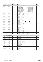
Page 67: ...ess 0x0000 None 0x0001 TOF 0x0002 EOF 0x0004 TON 0x0008 EON 20489 5009 1 Cycle counter 20490 500A 1 Operations to position I counter 20491 500B 1 Operations to position II counter 20492 500C 1 Fault signal 0 None 1 Alarm 2 Fault 20493 500D 1 Alarm fault code 0 None 1 F00 Op Fct 2 F03 Neutral 3 F11 FLT 1 4 F21 FLT 2 5 F12 ALR 1 6 F22 ALR 2 7 F13 ROT 1 8 F23 ROT 2 9 F14 CAP 1 10 F24 CAP 2 11 F15 PWR...

Page 68: ...4 5112 1 Source II Phase 2 neutral voltage V2 V 100 20755 5113 1 Source II Phase 3 neutral voltage V3 V 100 20756 5114 1 Source II Frequency Hz 100 Time delays 20992 5200 1 Source I loss 1FT S 20993 5201 1 Source I return 1RT S 20995 5203 1 Source I return to 0 1OT S 20999 5207 1 Source II loss 2FT S 21000 5208 1 Source II return 2RT Appli M M or Source II Stabilisation 2AT Appli M G S 21001 5209 ...

Page 69: ...oad 0x06 Configure EON External On Load 0x07 Cancel EOF External Off Load 0x08 Cancel EON External On Load 0x10 Cancel alarms and faults 0x11 Configure FT1 0x12 Configure FT2 0x13 Configure AL1 0x14 Configure AL2 21585 5451 1 Operating mode configuration 3 Auto 4 Inhibit 5 Control Other Unchanged 21586 5452 1 Priority configuration 0 Network 1 Source I 2 Source II Other Unchanged 21587 5453 1 Posi...

Page 70: ...4 1 Off Load external operation request timer end E7T S 21781 5515 1 Off Load external operation request timer duration E6T S 21782 5516 1 Load shedding timer LST S Threshold configurations 21840 5550 1 Source I Voltage upper threshold 21841 5551 1 Source I Voltage upper threshold hysteresis 21842 5552 1 Source I Voltage lower threshold 21843 5553 1 Source I Voltage lower threshold hysteresis 2184...

Page 71: ...z 22101 5655 1 Application type 0 Network Network M M 1 Network genset M G 22103 5657 1 Genset starting relay 0 NO 1 NC 22104 5658 1 PRIO NET 0 none 1 source I 2 Source II 22105 5659 1 PRIO TON 0 NO 1 YES 22106 565A 1 PRIO EON 0 NO 1 YES 22107 565B 1 RETRANS 0 NO 1 YES 22108 565C 1 RETURN O 0 NO 1 YES 22110 565E 1 2ND TRIP 0 NO 1 YES 22111 565F 1 MOD AUT 0 NO 1 YES 22112 5660 1 BACKLIGHT 0 OFF 1 O...

Page 72: ...ts Outputs 1 INH 1 S1A 2 tol 2 S2A 3 TOF 3 SCA 4 EON 4 AC1 5 EOF 5 AC2 6 MSR 6 AC0 7 RTC 7 LO1 8 PRI 8 LO2 9 SS1 9 LSC 10 SS2 10 FLT 11 PS1 11 POP 12 PS2 12 CP1 13 PS0 13 CP2 14 AL1 14 CP3 15 AL2 16 FT1 17 FT2 18 OA1 19 OA2 20 RST 21 LSI ...

Page 73: ...f the critical level and application where the product is installed should form an essential and integral part of the maintenance plan Good engineering practice is imperative whilst all necessary precautions must be taken to ensure that the intervention whether directly or indirectly remains safe in all aspects The use of any Megohmmeter is prohibited on this product as the connection terminals ar...

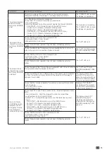
Page 74: ...d FREQ LEVELS menus If using an Auto transformer proceed as follows Step 1 Enter programming mode Step 2 In the SETUP menu configure the NETWORK parameter to 3NBL Step 3 In the SETUP menu configure the NEUTRAL parameter location of Neutral to left or right depending on where the neutral is connected Step 4 Exit programming mode The Emergency SOURCE Availability LED does not come on Press the LED t...

Page 75: ...hat automatic operation has not been inhibited by external orders Check the state of the Priority Source Availability LED If it is off refer to the symptom concerned higher in the list The AUT and Priority SOURCE Availability LEDs are lit Check the setting of 1RT 1 Return Timer If necessary use a stopwatch to check the switch to Priority SOURCE The duration of this delay is between 0 and 3600s The...

Page 76: ...dle Manual switchover from position 1 to position 2 is executed clockwise The return operation is executed anticlockwise The product can be switched over using the handle Check that the product is not padlocked Use the handle extension on the ALLEN key to check that the appropriate adjustment torque is applied When using a single AC check that the length of the screws used is not greater than 20 m...

Page 77: ...77 EN ATyS p M 542935E SOCOMEC ...

Page 78: ...surement of electrical parameters Energy management A worldwide presence 80countries where our brand is distributed 12production sites France x3 Italy x2 Tunisia India China x2 USA x3 ENERGY STORAGE POWER CONVERSION POWER MONITORING POWER SWITCHING EXPERT SERVICES EXPERT SERVICES 28subsidiaries and commercial locations Algeria Australia Belgium China Canada Dubai United Arab Emirates France German...

Reviews: