background image

ITYS PRO

1 0 - 1 5 - 2 0   k V A

Installations- und bedienungsanleitung 

DE

Installation and operating manual 

EN


Manual de instalación y uso 

ES


Manuel d’installation et d’utilisation 

FR


Manuale di installazione e uso 

IT


安装及操作手册 

ZH

Summary of Contents for ITYS PRO 10

Page 1: ...O 1 0 1 5 2 0 k V A Installations und bedienungsanleitung DE Installation and operating manual EN Manual de instalaci n y uso ES Manuel d installation et d utilisation FR Manuale di installazione e us...

Page 2: ...he packaging and in the manual in the event of long periods of storage or UPS inactivity SOCOMEC may at its own discretion opt for the repair of the product or the replacement of faulty or defective p...

Page 3: ...RATELY 3 1 MODELS 18 5 3 MAINS AND AUXILIARY MAINS CONNECTED IN COMMON 3 3 MODELS 18 5 4 EXTERNAL BATTERY CONNECTION 19 6 CONTROL PANEL 20 7 MENU 21 7 1 DISPLAY OVERVIEW 21 7 2 MENU TREE 24 7 3 MENU F...

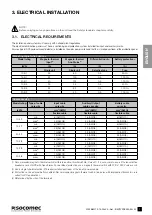
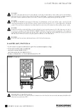
Page 4: ...for implementing the backfeed protection with the use of AC input line isolation devices external to the UPS Refer to Electrical requirements chapter DANGER RISK OF ELECTRIC SHOCK Before carrying out...

Page 5: ...T TO WORK SAFELY DANGER HIGH VOLTAGE BLACK YELLOW READ THE USER INSTRUCTIONS CAREFULLY READ THE USER MANUAL BEFORE PERFORMING ANY OPERATIONS PROTECTIVE EARTH TERMINAL PE BATTERIES AND RELATED PARTS CO...

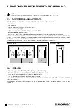
Page 6: ...the Technical specification chapter The connections and the UPS breakers need to be accessible from the rear a space of at least 1 5 meters should be left at the front of the UPS for maintenance purpo...

Page 7: ...e Model rating Type of cable core size Input cable core size Auxiliary Output cable core size Battery cable core size kVA mm2 AWG mm2 AWG mm2 AWG flexible cable flexible cable flexible cable 10 3 1 mi...

Page 8: ...have sufficient current carrying capacity The PE cable core size has to be chosen according to the PROTECTIVE CURRENT RATING of the earth circuit that depends on the provision and location of over cu...

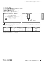
Page 9: ...interruptible Power System UPS Then check for Hazardous Voltage between all terminals including the protective earth Risk of Voltage Backfeed B L1 L2 L3 N NOTE Use a 220 240 V release coil with integr...

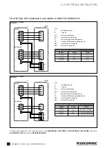
Page 10: ...ion device T2 Aux Mains BKF power isolation device XB2 Aux Mains BKF connector XB3 Mains BKF connector Key A Distribution panel B Trip coil X10 Mains terminal block X40 Aux Mains terminal block T1 Mai...

Page 11: ...r isolation device XB2 Not connected XB3 Mains BKF connector Remote switches rated current Model T1 A 10 3 3 25 15 3 3 32 20 3 3 40 PROTECTION WITH MAINS AND AUX MAINS CONNECTED TOGETHER L1 L2 L3 N X1...

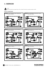
Page 12: ...nd Auxiliary mains connected separately with internal batteries 4 5 Mains and Auxiliary mains connected separately with output transformer 4 OVERVIEW NOTE Before carrying out any operations on the uni...

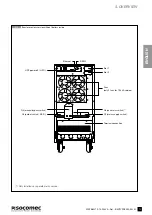
Page 13: ...mer less version without battery inside Fans only 2 fans for 10 kVA version UPS power off U P O Q5 manual bypass switch Q4 aux mains switch 1 Q1 mains supply switch Terminal connection Q3 output switc...

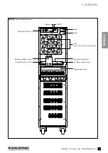
Page 14: ...less version with battery inside 4 OVERVIEW Fans only 2 fans for the 10 kVA version UPS power off U P O Q5 manual bypass switch Q4 aux mains switch 1 Q1 mains supply switch Terminal connection Q3 out...

Page 15: ...NGLISH 4 9 Transformer based version 4 OVERVIEW Fans only 2 fans for the 10 kVA version UPS power off U P O Q5 manual bypass switch Q4 aux mains switch 1 Q1 mains supply switch Terminal connection Q3...

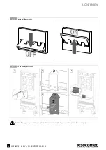
Page 16: ...RO 10 15 20 kVA Ref IOMITYPRXX00 EN 03 4 10 Position of the switches 4 11 Q5 manual bypass switch 4 OVERVIEW A Follow the bypass procedure chapter 8 before removing the bypass switch protection cover...

Page 17: ...ES WITH ANTI INTRUSION FERRULE Remove the protection Remove the pre cut cable entry slot Loosen the cable gland Cross the cable to the cable gland Carry out all the required connection Once the connec...

Page 18: ...LS Earth Cable terminal characteristic M6 screw tightening torque 3 5 4 5 Nm L12 L22 L32 OUTPUT X 50 N2 L11 L21 L31 AUXILIARY MAINS X 40 N1 L1 L2 L3 B MAINS SUPPLY X 10 EXT BATTERY X 20 N B L12 OUTPUT...

Page 19: ...the cable cross section refer to Electrical requirements chapter WARNING Cabling errors with inversion of battery polarity may cause permanent damage to the equipment Reassemble the plastic terminal b...

Page 20: ...dundancy lost Flashing yellow Maintenance period expired In maintenance mode On bypass with an alarm present Bypass procedure in progress Flashing yellow red A critical alarm occurs Load supplied But...

Page 21: ...n inverter normal mode ON AUTO BYPASS The output load is on static bypass UNIT AVAILABLE Energy saver is active inverter is off temporarily STANDBY Unit in standby LOAD OFF The output load is off Func...

Page 22: ...ify the energy flow solid enabled dotted disabled ADDITIONAL ICONS key icon displayed if the keypad is locked 7 1 4 7 1 5 ON INVERTER ON INVERTER General alarm On maintenance bypass Bypass mode or Eco...

Page 23: ...harging Level reached is ashing Battery open Battery discharged Battery in alarm 7 1 6 ON INVERTER ON INVERTER ECO ON INVERTER ECO 0 0 20 60 80 80 100 100 Maintenance bypass activated Load value not a...

Page 24: ...BATTERY TEST 1 LED TEST SETTINGS PREFERENCES LANGUAGE DATE TIME BUZZER PASSWORD REMOTE CONTROLS UPS SETTINGS 3 OUTPUT BATTERY SETTINGS BACKFEED CONNECTIVITY NETWORK PARAMETERS NETWORK SERVICES RS232 P...

Page 25: ...TING PROCEDURES PARAGRAPH ECO MODE ON OFF this function sets resets the ECO MODE BATTERY TEST this function checks first if the conditions to do the tests are available and after it returns the result...

Page 26: ...ical number of cells capacity charge current Risk of damage to load or batteries SERVICE MENU This menu is reserved for support service personnel and holds UPS identification data and utilities for so...

Page 27: ...ING ON Supply power to the UPS Put switch Q1 into position ON Wait for the display to switch on Enter MAIN MENU CONTROLS START PROCEDURE Carry out the operations indicated on the display 8 2 SWITCHING...

Page 28: ...Carry out the operations indicated on the display 8 4 OPERATION IN HIGH EFFICIENCY MODE The UPS makes it possible to select a programmable economy operating mode that can increase overall efficiency...

Page 29: ...y quickly NOTE This operation interrupts the supply to the output load from both inverters and automatic bypass If the UPS is operating from the maintenance bypass with the mains present the emergency...

Page 30: ...option kit Mechanical Available as stardand NOTE For slots positions see figures 4 5 and 4 6 MODBUS MODBUS is a Master Slaves protocol in which the UPS is one of the slaves The Master sends a request...

Page 31: ...ESS NOTE The web server is a read only interface no commands settings can be sent to the UPS remotely To set the network configuration enter SETTINGS CONNECTIVITY NETWORK PARAMETERS In this menu it s...

Page 32: ...rogrammable Alarm 10 In3 Battery Temperature Alarm 10 Out1 General Alarm 10 Out2 Battery Temperature Alarm 10 Out3 Overload or Redundancy lost 10 Out4 Programmable Alarm 10 SAFETY DIP1 OFF DIP2 ON IN...

Page 33: ...33 ITYS PRO 10 15 20 kVA Ref IOMITYPRXX00 EN 03 ENGLISH 9 STANDARD FEATURES AND OPTIONS 9 4 IP31 ROOF NOTE For further information refer to the IP31 assembling instruction...

Page 34: ...d Internet browser i e Internet Explorer Chrome etc using the UPS IP address at port 55000 http UPS_IP_ADDRESS 55000 To get UPS IP address enter MAIN MENU SETTINGS CONNECTIVITY NETWORK PARAMETERS IP A...

Page 35: ...kage has been uploaded Wait until all the firmware items in the table have been upgraded Finished OK Once the upgrading procedure has been completed the Communication board will be reset so you will l...

Page 36: ...ted life time of the batteries is very much dependent on operating conditions number of charging and discharging cycles load rate temperature NOTE Batteries must only be replaced with batteries recomm...

Page 37: ...critical There is a problem on the rectifier Please contact Service A035 Rectifier input supply not ok The input mains supply is out of tolerance Verify that the input voltage and frequency are withi...

Page 38: ...ingle phase selectable 208 3 220 230 240 1 3 3 400 three phase selectable 360 3 380 400 415 1 Frequency Hz 50 60 2 Hz from 1 Hz to 5 Hz with GENSET Nominal apparent power Sn 0 C to 40 C kVA 10 15 20 N...

Page 39: ...0 1 Type and performance EN 62040 3 VFI SS 111 EMC EN 62040 2 CLASS C2 Product certification CE Protection level IP20 IP31 on request compliant with 60529 1 With batteries fully discharged Call SOCOME...

Page 40: ...kW 8 9 10 10 9 12 13 3 15 1 16 3 18 17 8 20 2 21 8 24 Crest factor at 25 C 2 7 Total output voltage harmonic distortion THDv 1 with linear load Environment Operating temperature C 0 40 15 25 recommen...

Page 41: ...with GENSET Nominal apparent power Sn 0 C to 40 C kVA 10 15 20 Nominal active power Pn 0 C to 40 C kW 9 13 5 18 Overload 25 C Vin 207 Vrms Vbat 300 V 4 10 minutes 5 minutes 1 minute 30 seconds kW 10...

Page 42: ......

Page 43: ......

Page 44: ...ITYPRXX00 EN 03 IOMITYPRXX00 EN 03 08 2016 Manufacturer SOCOMEC ELECTRIC SHANGHAI CO LTD Address Building A30 No 5399 Waiqingsong Road Qing Pu Shanghai P R C EU Importer SICON S R L Address Via Sila 1...

Reviews: