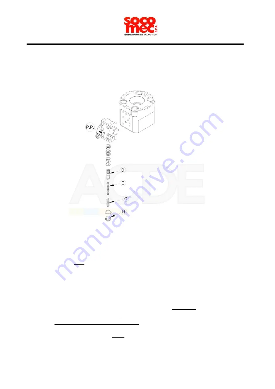
6 Regulations and greasing system
6.1 How to regulate the pressure control valve
In order to verify the setting of the valve, you have to proceed as follows:
1. Connect a manometer (with the scale 300-400 bar) to a capillary hose 8-10 m long
to get the working pressure from a safe distance.
2. Install the other extremity of the hose with the plug “P.P.”
3. Operate the hammer and check the working pressure on the manometer.
If the pressure is lower than what indicated by the manufacturer (see par. 2.2 “Technical features”)
you have to:
A. Remove the plug “H”
B. Take off the spring “C”
C. Insert, between the spring “C” and the collar of the small piston “D”, the necessary number
of washers “E”, until the correct working pressure is achieved. In order to know which is the
correct number of washers to add, you have to consider that
one washer
makes a variation
on the working pressure of
7 bar
. The washers must have the following characteristics:
thickness 0.5 mm, Øi=14mm, Øe=21.8 mm.
If the measured working pressure is higher than what indicated by the manufacturer (see par. 2.2
“Technical features”) you have to:
D. Repeat the same steps mentioned above (A+B);
E. Remove the necessary number of washers to get the right working pressure as explained
above.
REGULATIONS AND GREASING SYSTEM
25
Page
of 48
6
Nederland B.V.
Summary of Contents for MDO 1600 TS
Page 34: ...44 39 41 43 45 36 35 38 40 42 46 37 STROKE CHANGER 34 Page of 48 10 Nederland B V ...
Page 40: ...101 96 98 100 99 97 DISTRIBUTOR GROUP 40 Page of 48 13 Nederland B V ...
Page 42: ...107 104 106 101 105 109 108 103 102 ACCUMULATOR GROUP 42 Page of 48 14 Nederland B V ...
Page 46: ...129 132 125 134 127 128 126 133 130 133 131 GREASING SYSTEM 46 Page of 48 16 Nederland B V ...


