9
SUNSYS FJB
- Ref.: IOMSUNIFXX01-GB 00
ENGLISH
No. of
strings
Device
rating
Cable gland
(marked A)
Cable gland
(Identifi ed
B-R)
Min. cable
diameter
(mm)
Max. cable
diameter
(mm)
Min. cable
cross-
section
(mm²)
Max. cable
cross-
section
(mm²)
8
160 A
ISO 25
/
13
19
35
120
12
160A
ISO 32
/
15
25
95
120
16
200A
ISO 32
/
15
25
95
120
24
320 A
ISO 40
/
21
32
120
240
All types
/
/
ISO 16
5
10
-
6
Tightening torque of the power cables connecting screws of the DC switch-disconnector:
DC switch disconnector
type
Confi guration (Nb of
strings)
Connecting screws
Tightening torque (Nm)
With remote tripping
8 – 12 – 16
M8
14Nm
24
M10
31Nm
With manual tripping
8 – 12 – 16 - 24
M10
24Nm
The interphase barriers of the DC switch shall be equipped during normal operation of the Field Junction Box
4.3. REMOTE CONTROLLED DC SWITCH
It is possible to insert a trip coil on the main switch so that the switch can be remote controlled. The trip coil is supplied as an
option (equipped by the customer).
4. ELECTRICAL REQUIREMENTS
4.2-1
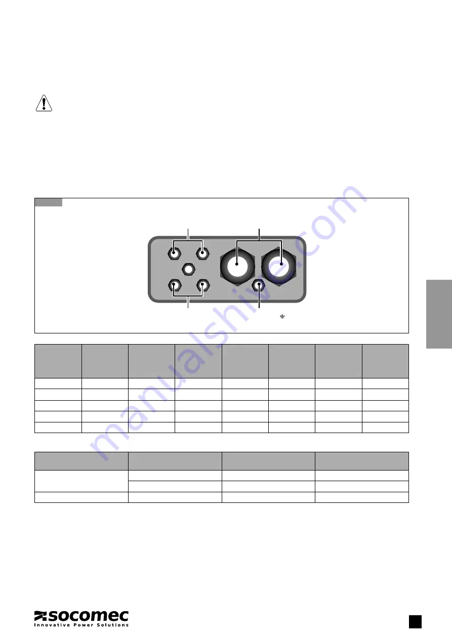
Cable gland plate of the DC switch-disconnector
PE
IS
O
PE
IS
O
PE
ISO
PE
ISO
PE
ISO
PE
ISO
4.1. ELECTRICAL INSTALLATION, OPERATION & MAINTENANCE
CAUTION:
RISK
OF
ELECTRIC
SHOCK
• Before starting any installation work, use personal protective equipment.
• During operation the temperature of some components may be high.
• Disconnect the DC switch-disconnector and then open all the fuse holders.
• Check the tightening torque of the fuse holder electrical connections before product installation.
4.2. DC SWITCH-DISCONNECTOR CABLES CONNECTIONS
• Switch-disconnector instructions must be respected.
• Do not remove the safety insulating screens separation between the terminals
A pre-break NO/NC contact is fi tted in standard on the DC switch-desconnector.
Reserved
(ISO16)
Reserved
(ISO16)
DC switch-disconnector
(ISO 25 to 40)
Surge protection
(
)
(ISO 16)


