19
SUNSYS H30-H30i
- Ref.: IOMSUNHMXX04-GB 00
ENGLISH
4. WIRING
4.3. Photovoltaic
fi
eld connection (DC)
DANGER!
• Risk of serious injury and even death!
• Before carrying out any photovoltaic field connection procedures, make sure the DC power switch is disconnected.
Use suitable cables for connection to the photovoltaic field. Size the cross-section of the wires in accordance with the maximum
photovoltaic field short-circuit current and so as to minimise cable conduction losses. The DC connectors supplied allow PV1-F
cables with a maximum cross-section of 6 mm
2
.
WARNING!
The DC connectors are polarised. Take care to perform wiring correctly, observing the polarities.
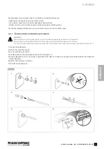
Figure 4.3.1-1 illustrates how to connect the positive pole of the photovoltaic field to the corresponding DC+ connector. The negative
pole can be connected in the same way.
4.3.1. Connection procedure
1 Unscrew the cable gland for the relevant DC connector and run the cable (which should have been stripped at the end by approx.
15 mm) through it.
2 Insert the cable into the connector as far as it will go.
3 Press the terminal downwards until it clicks into position.
4 Make sure the cable is fixed in position securely. The cable is properly secured if the wires can be seen inside the terminal chamber.
5 Push the screw connection onto the threading.
6 Screw on the cable gland.
7 Plug the connectors into the appropriate DC inputs on the inverter.
1
2
3-4
7
5-6
15 mm
4.3.1-1
Positive pole connection illustration
DC+ cable
Summary of Contents for SUNSYS H30
Page 4: ...4 SUNSYS H30 H30i Ref IOMSUNHMXX04 GB 00 4 ...
Page 37: ......
Page 38: ......
Page 39: ......

