24
SUNSYS H30-H30i
- Ref.: IOMSUNHMXX04-GB 00
24
5. COMMISSIONING
WARNING!
Do not place objects of any kind on top of the inverter during operation.
DANGER: RISK OF BURNS
The outer casing temperature can reach 70°C during normal operation. Danger may occur owing to hot surface.
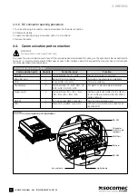
After installation, make sure the AC, DC, and communication connections have been carried out correctly. When there is enough
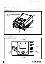
radiation, the device begins to work automatically. Please refer to the LCD display and the control panel, illustrated in figure 2.3.1-
1. The display includes an LCD screen and inverter LEDs status. The LEDs turn different colours to represent the various inverter
operating statuses. Refer to table 7.2-1 for further information on the LEDs.
5.1. Startup
procedure
Follow the step-by-step procedure below to commission the inverter.
5.1.1.
Checking the direct current (DC) and alternating current (AC) voltage
To check the DC voltage of the photovoltaic field:
1. Uncover the panels and expose them to direct sunlight. The sunlight must be intense enough to produce the required output voltage.
2. Measure the no-load DC voltage of the photovoltaic panels, between the positive (+) and negative (-) poles. This voltage must be
between 300 and 550 V in direct current (DC).
To check the AC mains network voltage:
3. Close the switch on the main switchboard.
4. Use an AC voltmeter to measure the no-load mains network AC voltage between L and N. Make sure the voltage is close to the rated value.
5.1.2. Starting up the inverter
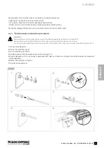
5. Set the DC and AC disconnection switches to ON
1
.
6. Check the inverter LCD display. The first time the inverter is switched on, you must follow the startup wizard (see chapter 5.2
"Configuration").
7. Once this startup wizard is complete, the inverter performs an autotest and begins running, with the steadily lit green LED signalling
correct operation. This means that there is enough solar radiation to release energy into the network.
8. If the checks have not yielded positive results, the unit will repeat the procedure so that all parameters fall within the range. The
green LED flashes during this phase.
1
The two devices may be closed in any order, there is no priority.
Summary of Contents for SUNSYS H30
Page 4: ...4 SUNSYS H30 H30i Ref IOMSUNHMXX04 GB 00 4 ...
Page 37: ......
Page 38: ......
Page 39: ......

