EN
Constant inlet and impulsion pressure control.
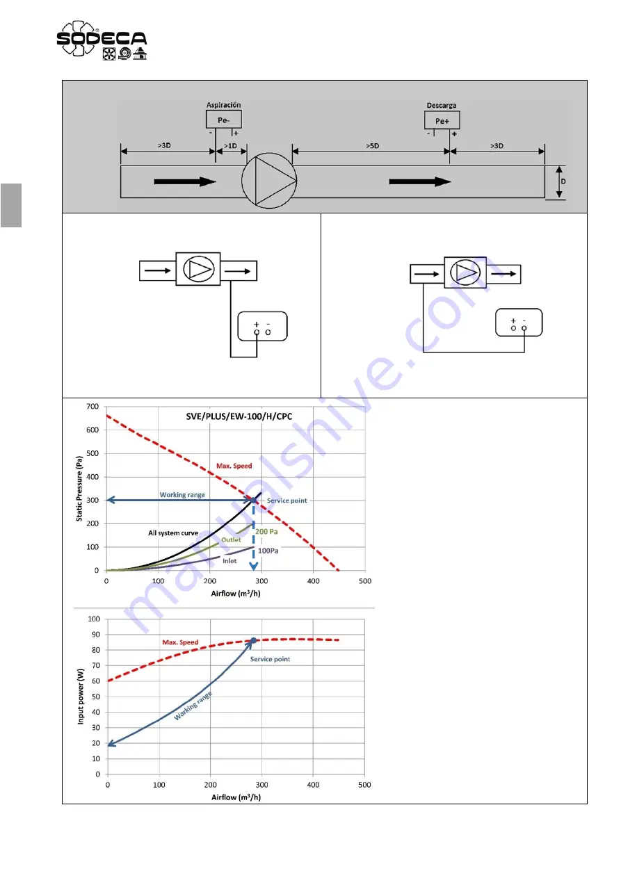
Fig.1 Impulsion pressure control.
Connection diagram between the CPC device and the fan.
Connect the positive connection of the CPC to the fan
outlet nozzle connection.
Fig.2 Inlet pressure control
Connection diagram between the CPC device and the fan.
Connect the negative connection of the CPC to the fan
inlet nozzle connection.
Fig.1
Fig.2
In this type of installation the
Set Point
of
the CPC
DOES NOT
coincide with the
total load loss of the system.
Once the service point flow rate has been
established, the load loss on inlet and on
impulsion will have to be taken separately
in this flow rate.
Depending on where the CPC is
connected to the installation, impulsion
(Fig.1) or inlet (Fig.2), the
Set Point
to
be programmed will be the load loss on
discharge or intake in the service point
flow rate.
In this graph used as an example, the
pressure value to be programmed is
200 Pa for an installation like the one
in
Figure 2.
For an installation like the
one in
Figure 1
it will be 100 Pa.


