HYD 3K~6K-EP
User manual
Copyright © Shenzhen SOFARSOLAR Co., Ltd
。
- 29 -
Table 4-7 Function description of the terminal
Pin NO.
Pin name
Description
Connected to (RRCR)
8
L1
Relay contact 1 input
K1 - Relay 1 output
9
L2
Relay contact 2 input
K2 - Relay 2 output
10
L3
Relay contact 3 input
K3 - Relay 3 output
11
L4
Relay contact 4 input
K4 - Relay 4 output
7
G
GND
Relays common node
Table 4-8 The inverter is preconfigured to the following RRCR power levels,close is 1, open is 0
L1
L2
L3
L4
Active Power
Cos(φ)
1
0
0
0
0%
1
0
1
0
0
30%
1
0
0
1
0
60%
1
0
0
0
1
100%
1
(
c
)
Logic interface for EN50549-1:2019, is in order to cease active power output
within five seconds following an instruction being received at the input
interface.
Fig.4-13 Inverter – RRCR Connection
Table 4-9 Function description of the terminal
Pin NO.
Pin name
Description
Connected to (RRCR)
8
L1
Relay contact 1 input
K1 - Relay 1 output
7
G
GND
K1 - Relay 1 output
Table 4-10 The inverter is preconfigured to the following RRCR power levels,close is 1, open is 0
L1
Active Power
Power drop rate
Cos(φ)
1
0%
<
5 seconds
1
0
100%
/
1
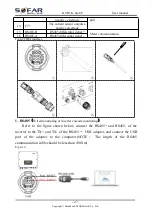
3.Meter/CT
PIN15 and PIN16
are used for meter communication, the electricity meter is
shown in the fig.
①
, PIN15 and PIN16 correspond to 7,8 respectively on the
electricity meter, as shown in fig.
③
.
The connection mode is shown in fig.
②
. The 1/2 and 3/4 on the electricity
meter are connected to voltage signals L and N respectively. And the current needs
to be connected through the current transformer,5,6 correspond to the current


