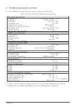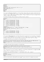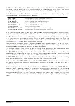
mon#sendp 5
send 5 msgs
mon#
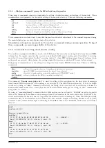
The command
”reset”
performs the module reset. After each reset the system starts with the parameters that are
stored in FLASH memory. If the current configuration should be used after reset, it is necessary to store it into the
FLASH before reset (see paragraph
). Example of using of ”reset” command:
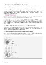
cfg\#reset
-- Reset code 0x14050302 --
SFT Reset
SW version 0.01, date Jan 18 2019
Monitor started ..
cfg#
By
”?”
command the list of all configuration commands with their brief description (”Help”) can be displayed.
Example of using this command can be found in the initial part of section
3.1.8
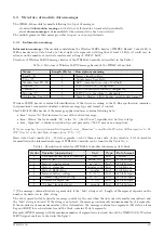
Displaying of other operational entries in the list of parameters
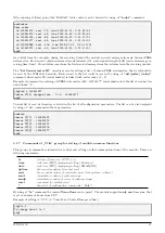
In the lower part of the list of all configuration parameters there are some additional
identification and opera-
tional parameters of the module.
, that are of
”
read only” type. There are following parameters:
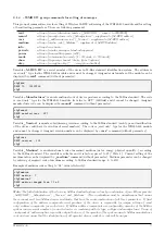
Next send : 29 min.
No. sent : 1 msg(s)
No. recv : 0 msg(s)
Conf. version : 7
SW version 1.02, date Jul 31 2020
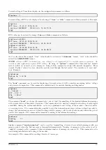
In the first part there is an information about sent messages. Parameter
”Next send”
means remaining time to
the next broadcasting of info message.
”No. sent”
and
”No. recv”
indicate numbers of received/transmitted
Wireless M-Bus messages.
In the
”Conf. version”
row there is a current version (number) of configuration set, that increases with each
storing of the configuration into the FLASH memory. The number is cleared by erasure of FLASH memory. In the
”SW version”
row there is a module software version and release date.
3.2
Setting of parameters by using of optical converter
The module i equipped with the
”
IRDA” infrared optical interface, that can be used for configuration through the
”
USB-IRDA”
converter (USB-to-optic) or through the
”
BT-IRDA”
converter (Bluetooth-to-optic).
All parameters that is necessary to set-up during common operation can be configured by
”
USB-IRDA”
converter.
The settings can be performed through the transparent casing without necessity to open the module’s cover. This
is the significant advantage especially if the module is used in humid environment and has been sealed by additional
silicon filling (additional adaptation for IP-68 proofing).
Any changes in module’s settings can be performed in
Module configuration table
that opens by click on the
”
Read device” button in
”
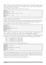
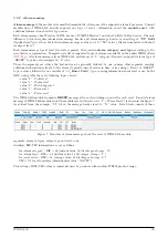
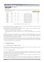
WACO OptoConf” program window. View of configuration table is depicted in figure
In the
upper section of the table
there are
”
read only” type of parameters (factory settings) that refer to the
identification of the module and its components. There are following parameters:
Device name
device name by manufacturer
Device type
device type by manufacturer
Device subtype
device subtype by manufacturer
Serial No.
device serial number (as well MBUS-ID in M-Bus address)
HW Version
hardware version by manufacturer
HW Revision
hardware revision by manufacturer
SW Version
software version by manufacturer
SW Revision
software revision by manufacturer
Manufacturer
MBUS Manufacturer code
Version
MBUS-Version in M-Bus address
WB169-430
13

