•
do not open the module, if not really necessary! Rewrite ID (serial number) of original meter to the ID of
new meter with using of USB-IRDA/BT-IRDA converter;
•
check in ”RADAR” mode, whether the new meter is in radio reach of the module and whether the read value
corresponds to watermeter mechanical counter;
•
if wireless configuration is not possible, check the antifraud seal and open the module. Potential damage of
antifraud seal should be solved according to the internal rules of each customer/project;
•
unscrew two screws on the sides of the box (beside the cable bushings), loosen the cap of the module and slide
out the base from the cap;
•
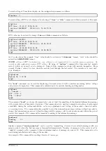
by using of ”sid [index] [value]” command set ID (serial number) of new watermeter by rewriting of original
ID value (see paragraph
”Commands for setting of watermeter reading”.
•
by using of ”recvwin” and ”radar” commands (see paragraph
check, whether the new meter is in radio
reach of the module and whether the read value corresponds to watermeter mechanical counter;
•
fill in the required documentation for the meter replacement (mounting sheet), precisely write down the value
of the mechanical counter of the new meter;
•
cover the module and seal it according to the instructions in paragraph
. Alternatively wait for the first
reading and cover the module afterwards.
•
if possible, arrange making of all appropriate changes in the database of the remote reading system immedi-
ately.
4.8
Module dismantling
When dismantling, open the module, switch off battery, disconnect antenna cable and dismantle the cap from the
wall, pad or pipe. Put the module parts back together by mounting of the cap on the module base. After the
dismantling mark the module as
”
dismantled” and fill in the relevant documentation, prescribed for this situation
by the internal rules. If possible, arrange deactivation of the module in the database of remote reading system
immediately.
4.9
Functional check of the module
After putting the module into operation (or after each repair and replacing of the module) it is recommended
to check functionality of its broadcasting with using of common
”
Master” receiver, RF analyzer, or any other
convenient device.
If the WB169-430 module is connected to remote data collecting system with using of WB169-RFE gateway,
functionality of its broadcasting could be checked from any computer in
”
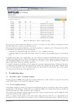
Radar” mode
by presence of module’s
signal in the
”
Radar” application. Open any WEB browser in the computer and enter IP-address of the module’s
superior WB169-RFE gateway. URL address of the gateway should be entered in
”
http://ip adresa/
” form and
search should be started after that. If an IP-connectivity between the computer and gateway is available, the website
of
”
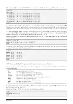
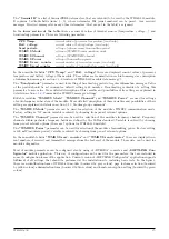
Radar” application opens (see figure
), where there is a table with last reports from all devices broadcasting
in the area of the gateway radio receiving (that work on the same frequency and with same communication mode).
The record of each device registered by gateway is displayed in a separate line where the following data can be seen:
•
equipment identification
•
receiving time of the last report from the equipment
•
indication of radio signal quality of received message (RSSI = Received Signal Strength Indicator)
If the
”
Radar” table is displayed in a sufficiently long time since the WB169-430 module was putting into operation
(or since its rebooting), the table should contain reports from meters and sensors connected to the module, including
the evaluation of the receiving quality. The
”
Radar” table displays only records received during last 2 hours.
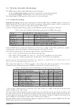
Survey of radio signal reception form iPERL watermeters can be performed in ”RADAR” mode by using of ”recvwin”
and ”radar” commands, either through configuration cable, or equivalent functions of optical converter;
4.10
Operation of the WB169-430 module
The WB169-430 module performs broadcasting of radio messages fully automatically. Take into consideration that
the broadcasting systems according to the Wireless M-BUS standard has no protection against interference during
transmission (a signal collision, which occurs when two modules broadcast at the same time), so that temporary
WB169-430
25

