It is clear from the example, that in the last 150 minutes the gateway has received messages from 9 terminals. Each
record contains the identification of the terminal device according to the Wireless M-Bus addressing system (ID,
Manufacturer, Version, Medium), the RSSI (Received Signal Strength Indicator) value, expressing the strength of
the received signal of the last message, and the time of receiving the last message from the device.
The command can be used (as an example) during gateway installation to examine signal strength from all devices
that the gateway is expected to operate. The information can be obtained even in initial time of installation when
the uplink connection to external servers is not available yet.
3.5
Display of WB169-RFG module parameters on the LCD screen
The WB169-RFG module is equipped on the front panel with a multi-line
LCD display
and
control buttons
,
which are used to display selected identification, configuration and operating data of the module.
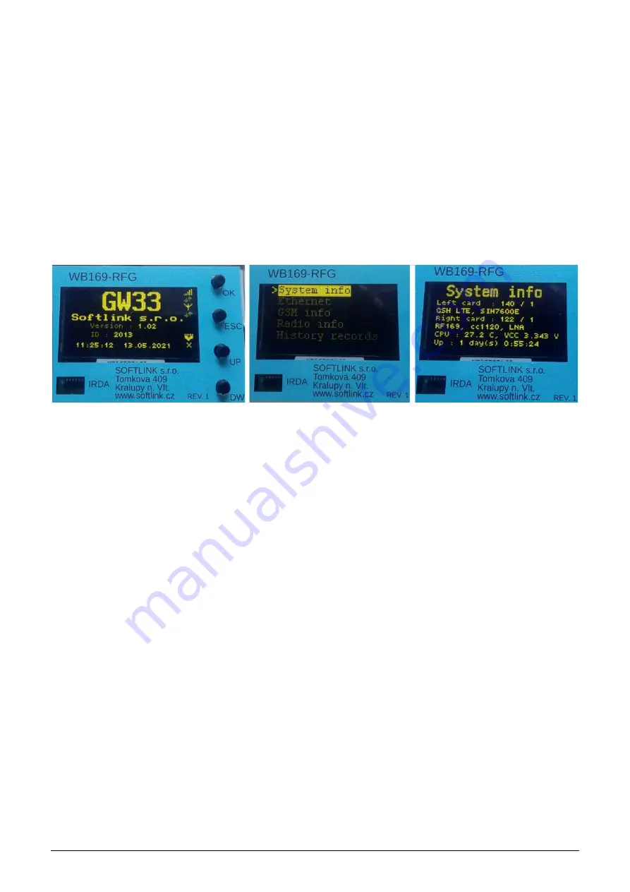
After switching on the module, the basic information about the module will be displayed on the LCD display (see
figure
on the left.
Figure 5: Display the main screen, main menu and system information
In addition to the manufacturer’s name, the text information includes the device type and version, the device ID
(serial number), and the system time. In the right part of the display there is a set of symbols that indicate the
status of module main communication channels:
•
on top there is a standard image of ”signal strength” symbolizing
GSM communication
with a graphical
representation of GSM signal strength. Below the symbol there are up and down arrows that flash each time
a message is received (down) and sent (up);
•
in the middle there is an antenna pictogram, symbolizing
communication over the 169 MHz radio
network
. Below the symbol there are also up and down arrows, which flash each time a Wireless M-Bus
message is received and sent;
•
at the bottom there is a data network pictogram symbolizing
communication via Ethernet port
. Below
the pictogram there is the ”X” symbol, which indicates that the system is not active.
By pressing the ”OK” button the main menu is displayed on the screen (see image
in the middle).
Selection of individual menu items can be performed by using of four control buttons at the right from the display,
which have the following functions:
•
use
”OK”
button for displaying the selected (marked) item from the menu;
•
use
”ESC”
button for return from the actual screen back to the menu;
•
use
”UP”
and
”DOWN”
buttons for moving in the menu or scrolling through the displayed records.
In the current version of the module, the basic information can be browsed via five menu items:
- configuration of hardware, sensor statuses and uptime (”System info”)
- Ethernet interface settings and statistics
- GSM interface settings and statistics
- 169 MHz RF-interface statistics (”CC1120”)
- list of current records of ”History” table
Appearance of individual screens can be seen in the figure
WB169-RFG
23


