Paramount MX User Guide
49 |
P a g e
Electronics Box Components
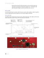
Mini USB Port (USB)
The mini USB 2.0 port accepts the square end of the standard mini USB cable connector (supplied with
the mount). Plug the rectangular end of the USB cable into the computer’s USB port.
TCS Status LED (TCS)
The TCS (for telescope control system) status light emitting diode (LED) constantly “pulsates” from
bright to faint and provides visual confirmation that the mount’s control system is operating normally.
When either LED is not illuminated after turning the mount on, it indicates a problem with the Bisque
TCS control system. Please contact Software Bisque technical support for further troubleshooting advice
(see “Getting Help” on page 10).
Right Ascension and Declination LEDs (Dec and RA)
The right ascension and declination LEDs show the status of the DC-servo motors. The LEDs blink while
the motors are being initialized. When the LED shines steadily, the motor is operating normally and
ready for use. If either LED is not illuminated, motor initialization failed. Turn the power off, then make
sure the joystick on the hand controller is centered, and the joystick button is not pressed before
repowering the mount.
Hardware Parking (Park Port)
Reserved for future use. This port will offer the ability to “hardware park” the Paramount MX using an
external voltage. This capability offers an alternative to parking the mount using
TheSkyX Professional
Edition
and can be crucial as a backup parking method when operating the mount remotely.
Hand Controller or Joystick Port (Joystick)
Plug the RJ12 connector on the Paramount MX hand controller or the Paramount ME joystick to
manually home and slew the mount. See “Hand Controller” on page 61 for details about this
component.
External Power (Input)
This 4-pin DC power connector can be used to run up to 20 Volts at up to 7.5 Amps power through the
mount to the Instrument Panel. See “Powering Devices (External Power Output)” on page 43 for
specifications for this connector. See “Appendix C: External Power Cable Sets” on page 128 for the pin
out specifications and connector part numbers.
The External Power connectors on the Instrument Panel and on the Electronics Box
do not
supply power
nor do they have anything to do with the Paramount MX power supply.
These connectors act as a conduit to route an external power source that is connected to
External Power connector located Electronics Box to the External Power connector in the
Instrument Panel.


