background image

GSR1700 CSX Operations Manual

 13

Receiver Components

Chapter 2

2.6.1

Remove the memory card

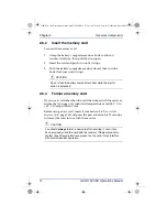
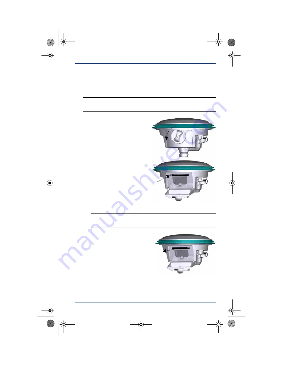
To remove the memory card:

1.

Grasp the battery 
compartment door knob and 
turn it counter clockwise, 
then pull the door open.

2.

Press the card ejector button 
once to extend it, then press 
it again to eject the card.

3.

Grasp the card and pull it 
straight out.

CAUTION

To prevent card damage or file corruption, 

turn the receiver off 

before 

removing or inserting the memory card. 

CAUTION

Do not close the battery compartment door while the ejector 
button is extended.

GSR1700 CSX Operations Manual (OM-1700CSX Rev 2, 750-1-0077).book  Page 13  Wednesday, December 3, 2008  2:32 PM

Summary of Contents for GSR1700 CSX

Page 1: ...GNSS Receiver System GSR1700 CSX Operations Manual ...

Page 2: ......

Page 3: ...Tplljb GNSS Receiver System GSR1700 CSX Operations Manual GSR1700 CSX Operations Manual OM 1700CSX Rev 2 750 1 0077 book Page i Wednesday December 3 2008 2 32 PM ...

Page 4: ...your rights with regard to this publication and the equipment SOKKIA and Spectrum are trademarks of SOKKIA TOPCON CO LTD SDR is a registered trademark of POINT Inc The following are trademarks or registered trademarks of their respective organizations The Bluetooth word mark and logos are owned by the Bluetooth SIG Inc and any use of such marks by POINT Inc is under license CompactFlash is a regis...

Page 5: ... performs best when handled with care This receiver can accept an input supply voltage in the range of 6 18 VDC Do not operate the receiver outside the specified voltage range When the battery compartment door is closed and latched and the port covers are closed the enclosure is sealed to provide protection against adverse environmental conditions To minimize the possibility of damage keep the bat...

Page 6: ...ii CE Statement GSR1700 CSX Operations Manual OM 1700CSX Rev 2 750 1 0077 book Page ii Wednesday December 3 2008 2 32 PM ...

Page 7: ... digital device pursuant to part 15 of the FCC Rules These limits are designed to provide reasonable protection against harmful interference in a residential installation This equipment generates uses and can radiate radio frequency energy and if not installed and used in accordance with the instructions may cause harmful interference to radio communications However there is no guarantee that inte...

Page 8: ...natural resources prudently and rationally Sustainable development advocates the reduction of wasteful consumption of natural resources and the prevention of pollution Waste electrical and electronic equipment WEEE is a regulated area Where the generation of waste cannot be avoided it should be reused or recovered for its material or energy WEEE products may be recognized by their wheeled bin labe...

Page 9: ...k Release Mount 10 2 4 Antenna 10 2 5 Battery 10 2 5 1 Remove or insert the battery 11 2 5 2 Charge the battery 12 2 6 Memory 12 2 6 1 Remove the memory card 13 2 6 2 Insert the memory card 14 2 6 3 Format a memory card 14 2 7 Wireless Communication 15 Chapter 3 Receiver Interface 16 3 1 Display Panel Overview 16 3 2 Power Button 17 3 3 Gauges 20 3 3 1 Battery life gauge 20 3 3 2 Satellite trackin...

Page 10: ... 4 4 Measure Antenna Height 40 4 4 1 Slant height method 40 4 4 2 Vertical and true vertical height methods 42 Chapter 5 Power Management 44 5 1 Turn the Receiver On and Off 44 5 2 Use an External Power Source 44 5 3 Power Peripheral Devices 45 5 4 Store the Receiver 45 5 5 Insufficient Power 45 Chapter 6 Collecting Data 47 6 1 Data Files 47 6 1 1 File names 47 6 1 2 Data storage capacity 48 6 1 3...

Page 11: ...al vii 6 3 3 Customizing POWERUP configurations 51 6 3 4 Perform a factory reset 52 Appendix A Technical Specifications 53 Index 57 GSR1700 CSX Operations Manual OM 1700CSX Rev 2 750 1 0077 book Page vii Wednesday December 3 2008 2 32 PM ...

Page 12: ...rts 7 5 Phase center offset label 10 6 Display panel components 16 7 Power button functions 18 8 Typical base setup 36 9 Typical rover setup 38 10 Slant height method 41 11 Vertical true vertical height methods 42 Figures GSR1700 CSX Operations Manual OM 1700CSX Rev 2 750 1 0077 book Page viii Wednesday December 3 2008 2 32 PM ...

Page 13: ...ccupation timer gauge baseline length mode 25 13 Occupation timer gauge elapsed time mode 25 14 Temperature issues 27 15 Voltage issues 27 16 Firmware issues 28 17 COM ports communication status LEDs 29 18 Wireless communication status LEDs 30 19 Audible annunciator conditions 31 20 Base setup components 36 21 Rover setup components 39 22 Slant height method 41 23 Vertical true vertical height met...

Page 14: ... x GSR1700 CSX Operations Manual 26 POWERUP configurations 51 27 GSR1700 CSX technical specifications 53 GSR1700 CSX Operations Manual OM 1700CSX Rev 2 750 1 0077 book Page x Wednesday December 3 2008 2 32 PM ...

Page 15: ...he receiver is ideal for static and stop and go kinematic surveying applications It is completely wireless and fits conveniently on the pole or tripod You can simply mount the receiver on a tripod or rover pole press the power button and begin collecting raw data You can also add the SDR data collection software to your setup in the field 1 2 Features The GSR1700 CSX is capable of the following mo...

Page 16: ...channels 14 L1 GPS 12 L1 GLONASS 2 SBAS Patented Pulse Aperture Correlator PAC technology for high accuracy GNSS measurement and multipath rejection Multiple Bluetooth wireless connectivity Multiple language voice messages or sounds to indicate receiver status One button survey operation Easy to read LED display status indicators Rugged shock resistant waterproof buoyant enclosure RoHS compliant C...

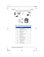
Page 17: ... Family Tools CD 6 Batteries 2 7 Battery charger 8 Battery charger cable 9 Operations Manual 10 GPS Field Book 11 Tape measure 12 Soft carrying case GNSS Receiver System At A Glance LED Display Panel Satellite Tracking Receiver Health Power Button Battery Life Memory Occupation Timer COM Port Status Bluetooth Status 1 4 3 6 7 8 9 2 5 11 12 10 GSR1700 CSX Operations Manual OM 1700CSX Rev 2 750 1 00...

Page 18: ...ce Guide Provides typical workflows for getting started using the GSR1700 CSX survey system and Spectrum Survey Table 3 Optional component descriptions Number Description 1 Data collector 2 Data collector mounting bracket 3 External battery 4 External battery cable 5 Communications cables various 1 2 3 4 5 GSR1700 CSX Operations Manual OM 1700CSX Rev 2 750 1 0077 book Page 4 Wednesday December 3 2...

Page 19: ...ctrum Survey User Guide and Help Describe how to process and adjust your data using Spectrum Survey software 1 5 Technical Assistance Technical support is available from the distributor where you purchased this product When you contact technical support please make sure you have the following information Your receiver information including serial number part number model and firmware version A des...

Page 20: ... by a shock absorbing rubber bumper The easy to use display panel incorporates single button operation and LED indicators that give you a view of your system status For details about the display panel features and how to use them see Chapter 3 Receiver Interface page 16 The battery compartment door provides access to the battery and the memory card Figure 3 Receiver components 1 2 3 4 5 6 GSR1700 ...

Page 21: ...criptions page 8 Both ports are protected from dust and water by attached covers You should leave these port covers closed whenever the ports are not in use Figure 4 Ports Table 4 Receiver components Component Description 1 Radome 2 Bumper 3 Display panel 4 Battery compartment 5 Ports 6 Quick release mount 1 2 GSR1700 CSX Operations Manual OM 1700CSX Rev 2 750 1 0077 book Page 7 Wednesday December...

Page 22: ...s an alternative to the receiver s battery 2 2 3 Cable usage When you are using cables ensure that you follow the instructions in this section The cables shown in Table 6 Cables for GSR1700 CSX page 9 are compatible with the GSR1700 CSX Table 5 Port descriptions Number Port Icon Description 1 Power Power input port 2 COM1 Communication port for accessory devices NOTE If you will be using both a ra...

Page 23: ... with a click It will then be locked in place 3 To remove a cable grasp the connector and pull straight out If there is a knurled ring grasp it and pull Table 6 Cables for GSR1700 CSX Cable Part number High power base station Satel UHF cable 403 0 0015 Serial to DB9 cable 403 0 0036 Y serial cable COM1 and COM2 403 0 60565003 Satel UHF cable 403 0 0058 Raven AirLink cable 402 0 9083 CAUTION Do not...

Page 24: ...ure 5 is located on the underside of the receiver and includes the vertical offset height value Figure 5 Phase center offset label You can measure the antenna slant height by hooking a tape measure onto the included measuring bar see Section 4 4 Measure Antenna Height page 40 2 5 Battery The receiver uses one rechargeable lithium ion battery It also contains an internal backup battery which allows...

Page 25: ...capable of running for 10 hours on a single charge The battery compartment door provides access to the main battery See Section 2 5 1 Remove or insert the battery page 11 for details The receiver can also be powered using an external power source For more information about additional power input see Section 5 2 Use an External Power Source page 44 2 5 1 Remove or insert the battery To remove the b...

Page 26: ...ery compartment door closed then turn the knob clockwise until it stops 2 5 2 Charge the battery To charge the battery use the included charger It takes approximately two hours to completely charge one battery and four hours to charge two batteries 2 6 Memory The receiver comes with an industrial grade removable CompactFlash card to support post processing applications For information about how ma...

Page 27: ... card ejector button once to extend it then press it again to eject the card 3 Grasp the card and pull it straight out CAUTION To prevent card damage or file corruption turn the receiver off before removing or inserting the memory card CAUTION Do not close the battery compartment door while the ejector button is extended GSR1700 CSX Operations Manual OM 1700CSX Rev 2 750 1 0077 book Page 13 Wednes...

Page 28: ...nly industrial temperature rated 40 C to 85 C CompactFlash cards Before using a new card insert it see Section 2 6 2 Insert the memory card page 14 and press the power button for 20 seconds to format the card for use with the receiver CAUTION Do not close the battery compartment door while the ejector button is extended CAUTION You should always format a new card after inserting it even if you hav...

Page 29: ...ll phones or other Bluetooth peripherals NOTE The receiver has a Bluetooth device ID that matches the receiver s serial number When connecting to the receiver using Bluetooth communications use this ID to confirm that you are connecting to the receiver you want See the Receiver Bluetooth Setup Quick Reference Guide for details about connecting from data collectors and PCs GSR1700 CSX Operations Ma...

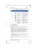
Page 30: ...rt you to receiver status and event conditions 3 1 Display Panel Overview The display panel components are illustrated in Figure 6 and described in Table 7 Figure 6 Display panel components Table 7 Display panel components Number Display Description Reference 1 Power button Section 3 2 Power Button page 17 2 Receiver health indicator Section 3 4 1 Receiver health page 26 2 1 3 4 5 6 8 7 GSR1700 CS...

Page 31: ...rated and summarized on page 18 3 Battery life gauge Section 3 3 1 Battery life gauge page 20 4 Satellite tracking gauge Section 3 3 2 Satellite tracking gauge page 22 5 Memory gauge Section 3 3 3 Memory gauge page 23 6 Occupation timer gauge Section 3 3 4 Occupation timer gauge page 24 7 Bluetooth wireless communication status LEDs Section 3 4 3 Wireless communication status page 30 8 COM port co...

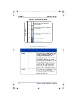
Page 32: ...will hear the Receiver Ready message or sound that indicates that the system is operational Note It is normal for the receiver health indicator LEDs to illuminate during startup Turn off 3 Press the button for 3 seconds and or until you hear the Power Off message or sound and only the top three battery life gauge LEDs illuminate Release to return to normal operation no action taken Release during ...

Page 33: ...e This action is irreversible If you are unsure about whether you want to delete all the files continue to hold the button longer than 25 seconds so that the receiver simply returns to normal operation To delete individual files from the memory use Planning or Spectrum Survey software on your PC Continue operation 25 When you hold the button longer than 25 seconds and you hear the Continue Operati...

Page 34: ...me The LED that is illuminated indicates the status 3 3 1 Battery life gauge The battery life gauge displays the battery life remaining on the internal battery When an external power source is connected the detected available voltage is indicated by a flashing LED NOTE If you remove the internal battery without having an external battery connected to the receiver LED 5 green and LED 1 red will fla...

Page 35: ...about using external power sources see Section 5 2 Use an External Power Source page 44 Table 9 Battery life gauge indicators Solid Flashing LED Internal battery time remaining hours External battery power available VDC 5 more than 8 14 0 to 18 0 4 6 to 8 11 0 to 14 0 3 3 to 6 10 6 to 11 0 2 1 to 3 10 1 to 10 6 1 less than 1 less than 10 1 NOTE The external battery status is specifically preconfig...

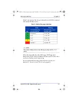
Page 36: ...ed lock both code and carrier Table 10 summarizes the values indicated by the satellite tracking gauge LEDs TIP For the most accurate survey results perform surveys with a minimum of six satellites if possible LED 1 red will be illuminated if the receiver is using only one two or three satellites which are insufficient for three dimensional positioning applications Table 10 Satellite tracking gaug...

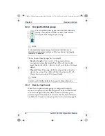
Page 37: ...o increase the available space If there is no memory card in the receiver all five LEDs will simultaneously flash Table 11 Memory gauge indicators LED Available memory 5 80 to 100 4 60 to 80 3 40 to 60 2 20 to 40 1 0 to 20 NOTE If an error occurs while data is being written to memory all five LEDs will simultaneously flash This might indicate an unformatted or incorrectly formatted card If possibl...

Page 38: ...sh See Section 3 3 4 2 Elapsed time mode page 25 for more details 3 3 4 1 Baseline length mode When the occupation timer gauge is configured to display receiver occupation by baseline length the LEDs will illuminate to show the length of baseline that can be successfully post processed given the amount of raw data that has been collected See Table 12 Occupation timer gauge baseline length mode pag...

Page 39: ...miles 3 sufficient data for 5 km 3 1 miles 2 sufficient data for 3 km 1 9 miles 1 sufficient data for 1 km 0 6 miles NOTE Table 12 provides estimates only Performance of the indicator depends on quality data being observed at other receivers no obstructions same satellites low multipath and so on If you are uncertain about the quality of the data collected log data for a longer period of time Tabl...

Page 40: ...iver is being operated outside its temperature range When there is a warning or error condition the LEDs illuminate in a sequence of six flashes The sequence of flashes is repeated after a short break Warning If both the yellow and the red LEDs flash first it is a warning condition Error If only the red LED flashes first it is an error condition The following sections describe the error warning co...

Page 41: ...If you see one of the sequences shown in Table 15 then the receiver is operating near or outside of the valid voltage range Ensure that the battery is charged or check your external power source Table 14 Temperature issues Sequence of flashes 1 2 3 4 5 6 R R Y R R Y R Y R Y R R Y R R Y R Y R R Y R Y R Y R Y R Y R Table 15 Voltage issues Sequence of flashes 1 2 3 4 5 6 R R Y R Y R R R R Y R Y R Y R...

Page 42: ...form a factory reset see Table 8 Power button functions page 18 3 If the error condition still persists check to see if the receiver is too hot If necessary let it cool down and then perform another factory reset 4 If the error condition is not resolved contact your local SOKKIA distributor Table 16 Firmware issues Sequence of flashes 1 2 3 4 5 6 R R Y R Y R R Y R TIP To assist in identifying the ...

Page 43: ...transmit and receive LED indicators are illuminated For more details about the COM ports see Section 2 2 1 Communication port page 8 NOTE See Section 2 2 Ports page 7 for details about the ports Table 17 COM ports communication status LEDs LED State Status Description Red Illuminated Data is being received by the receiver through the COM port Dark No data is being received through the COM port Gre...

Page 44: ...h connection has been established with another device for example a data collector Dark The internal Bluetooth device is off Red Flashing Data is being received by the receiver through the Bluetooth port Note The LED might flash briefly at times when data is not being received Dark No data is being received through the Bluetooth port Green Flashing Data is being transmitted from the receiver throu...

Page 45: ...erve battery life and the wireless communication status LEDs will stop flashing To restore power to the port turn the receiver off and then turn it on again If the port is used once or more during the first 30 minutes of operation the port will remain powered until the receiver is turned off NOTE Your receiver is preconfigured with either voice messages or sounds at a preset volume To modify these...

Page 46: ...button has been held down too long for any action to take place Release the power button to resume normal receiver operations once Battery Low The internal battery is low or if you are using only an external power source it is below the voltage threshold Note To ensure continued operation without interruption immediately insert a charged battery or connect an external power source continuous every...

Page 47: ...n internal memory continuous based on log rate or once Backup Battery Warning tone The receiver is operating on backup battery power Insert a charged battery to continue operation continuous every 2 seconds Backup Battery Critical tone The receiver is operating on backup battery power and less than 8 seconds remain before the receiver shuts down Insert a charged battery to avoid shutdown continuou...

Page 48: ...ent page 44 for more details about supplying power 2 Press the power button The receiver will turn on acquire and track satellites and issue a Receiver Ready message or sound when it completes the initialization Typically the receiver will then operate based on the POWERUP configuration See Section 6 3 Use the POWERUP Configuration page 50 for more information about POWERUP configurations 3 If you...

Page 49: ...nd when it completes 3 Connect to the receiver using Bluetooth You can use a Bluetooth USB adapter for example the one that is included with Spectrum Survey Suite to connect the receiver to a PC that does not have built in Bluetooth capability Refer to the Receiver Bluetooth Setup Quick Reference Guide for details 4 Communicate with the receiver For example use Spectrum Survey or Planning software...

Page 50: ... Description 1 GSR1700 CSX receiver 2 Measuring bara a The measuring bar is used to extend the area outward from the receiver so that the tape measure can extend to the ground clearing the tripod and tribrach 3 Tribrach adapter 4 Tribrach 5 Tripod 6 Tape measure 1 2 3 4 5 6 GSR1700 CSX Operations Manual OM 1700CSX Rev 2 750 1 0077 book Page 36 Wednesday December 3 2008 2 32 PM ...

Page 51: ... 5 Press the power button to turn on the receiver The receiver will initialize and issue a Receiver Ready message or sound when it completes 6 Use the receiver s display panel LEDs see Chapter 3 Receiver Interface page 16 to monitor the survey For example to verify that the data is being recorded to file ensure that the memory gauge is flashing To verify the receiver s occupation status or to veri...

Page 52: ...ns Manual Chapter 4 System Setup 4 3 2 Typical stop and go kinematic rover setup Figure 9 Typical rover setup 1 2 3 4 5 GSR1700 CSX Operations Manual OM 1700CSX Rev 2 750 1 0077 book Page 38 Wednesday December 3 2008 2 32 PM ...

Page 53: ...en it completes 6 Use the receiver s display panel LEDs to monitor the survey For example to verify that the data is being recorded to file ensure that the memory gauge is flashing see Section 3 3 3 Memory gauge page 23 7 Use Bluetooth communication to connect the data collector to the receiver Refer to the Receiver Bluetooth Setup Quick Reference Guide for details Table 21 Rover setup components ...

Page 54: ...eight methods page 42 2 Measure the distance between the antenna and the ground 3 Record your measurements in your field book or software 4 4 1 Slant height method Typically the slant height measuring method is used when you are using a tripod during static surveys or establishing a base station NOTE Accurately measuring and recording the antenna height is of critical importance Failure to accurat...

Page 55: ... the measuring bar to the survey mark on the ground 3 Record the slant height SH in your field book see Section 4 4 1 1 Record height in field book page 42 or in the Spectrum Survey or SDR software see Section 4 4 1 2 Record height in software page 42 Table 22 Slant height method Number Description 1 Radius R 120 mm 2 Slant height SH 3 Vertical offset value see Section 2 4 Antenna page 10 for deta...

Page 56: ...the bottom of the receiver and the phase center to the result of step 2 4 4 1 2 Record height in software The software Spectrum Survey or SDR will automatically compute the HI when you select the measurement method and enter the SH 4 4 2 Vertical and true vertical height methods Typically if you are surveying using a graduated range pole or fixed height tripod you will use the vertical or true ver...

Page 57: ...e the following steps to find the receiver s antenna height 1 Measure the vertical height of the range pole or tripod 2 Add the vertical offset between the bottom of the receiver and the phase center to the result of step 1 3 Record the true vertical height in your field book or in the Spectrum Survey or SDR software Table 23 Vertical true vertical height methods Number Description 1 Vertical heig...

Page 58: ...efore turning off 5 2 Use an External Power Source As an alternative to using the internal battery for example if the internal battery is discharged the receiver can also be powered using an external battery following the recommendations in this section When the external battery is discharged the receiver will automatically switch to using the internal battery If the internal battery does not have...

Page 59: ...5 Insufficient Power If the internal battery and any external power input voltage are below minimum operating parameters in other words if the main battery is depleted or external power is removed or insufficient the receiver will initiate a power down sequence It will turn off and become inactive If this happens you will not be able to turn the receiver on until you restore sufficient power To re...

Page 60: ...configuration see Section 6 3 Use the POWERUP Configuration page 50 In the case of a prolonged greater than 30 seconds power failure while logging data the receiver will save the data to internal memory and close the file before powering off If this occurs up to 10 seconds of data may be lost from the file CAUTION The receiver may also become inactive if the external power input is greater than th...

Page 61: ...me is stored in a single unique data file in memory Only one file is open and recorded to at a time You can transfer a file of collected data to a PC for post processing and adjustment using Spectrum Survey Suite software see Section 4 2 Set Up at the Office page 35 6 1 1 File names Auto generated file names consist of an eight character base followed by a pdc extension as follows pdc The eight ch...

Page 62: ...0 9 and A Z based on the presence of files previously logged on a particular day 15th session created that day is E Sample generated file name 1234025E pdc NOTE Instead of using the auto generated file name you can specify the file name using SDR software Table 24 Auto generated file name convention continued Part of file name Description Example Table 25 Hours of storagea a Based on 64 MB memory ...

Page 63: ...r a wireless connection or a cable you establish a communication link between the two devices and the data collector will control the behavior of the receiver When you turn on the receiver it will use its POWERUP configuration see Section 6 3 Use the POWERUP Configuration page 50 until the data collector takes control Commands sent to the receiver through the data collector will supersede the POWE...

Page 64: ...esent on the receiver unless you remove it The POWERUP configuration tells the receiver What type of data to collect for example observations ephemeris almanac The interval at which data should be collected for example every 10 seconds The antenna height The elevation mask The site name and number optional The COM port baud rates 6 3 2 Default POWERUP configurations Your receiver is preset with on...

Page 65: ...arded and the POWERUP configuration reverts to the factory default settings see Section 6 3 4 Perform a factory reset page 52 Table 26 POWERUP configurations Static 15 Static 10 Raw Observations Log to file Yes Yes Recording interval seconds 15 10 Minimum satellites to store an epoch 3 3 Elevation mask degrees 5 5 Peripheral Power Send power to data collector peripheral on COM1 No No NOTE Only one...

Page 66: ...lt factory POWERUP configuration see Section 3 2 Power Button page 17 The receiver will audibly indicate that a reset has occurred and will restart see Section 3 5 Audible Annunciator page 31 NOTE Data files on the receiver are not affected by a factory reset GSR1700 CSX Operations Manual OM 1700CSX Rev 2 750 1 0077 book Page 52 Wednesday December 3 2008 2 32 PM ...

Page 67: ...eraturea External battery 40 C to 55 C 40 F to 131 F Storage temperatureb 40 C to 60 C 40 F to 140 F Humidity 100 condensing Dust and waterproof IP67 Complete protection against dust ingress Protected against immersion up to 1 0 m 3 3 ft Pole dropc 2 m 6 6 ft drop Bump IEC 68 2 29 Test Eb 10g Shock IEC 68 2 27 Test Ea 30g Vibration profiles Random MIL STD 202G Method 214A Test Curve A Sinusoidal S...

Page 68: ...5 m DGPS DGNSS 0 45 m Post processed position accuracye Staticf H 5 mm 1 ppm V 8 mm 2 ppm Kinematic Stop and Gof H 10 mm 1 ppm V 12 mm 2 ppm Stand alone Position 1 8 m CEP Horizontal Multipath mitigation Pulse Apperture Correlator PAC technology Receiver limits Up to 18 288 m 60 000 feet in accordance with export licensing and 514 m s Power Requirements Power input External 6 VDC to 18 VDC Interna...

Page 69: ...Communication ports 2 x RS232i 2 x Bluetooth Standard Input Output RTCM RTCM V3 0 RTCA CMR CMR NMEA 0183 out PPS out Mark in Serial Electrical Format EIA TIA 232 E Serial EIA TIA 232 E Baud Rate COM1 4800 9600 default 19200 38400 57600 115200 230400 COM2 4800 9600 default 19200 38400 57600 115200 230400 Note COM port baud rates are limited to the equipment you are using with the receiver Serial si...

Page 70: ... standard Operation below 20 C will reduce battery life longevity b High temperature storage above 60 C can be offered but is not standard c Based on receiver without cables attached d Does not include any biases due to RF or antenna delay e Accuracy depends on the number of satellites used obstructions satellite geometry DOP occupation time multipath effects atmospheric conditions baseline length...

Page 71: ...tors 29 30 components receiver 6 15 system 2 4 configurations about 50 customizing 51 default 50 customer support 5 D data collecting 47 51 file naming 47 loss of 46 storage 47 48 transferring 35 default POWERUP configuration 50 deleting files 19 49 DGPS 2 display panel overview 16 17 See also gauges status indicators documentation 4 downloading data 35 E elapsed time timer setting 24 25 epoch rec...

Page 72: ...ons 32 33 gauge 23 removing inserting 13 14 messages See audible annunciator modes of operation 1 mount 10 N naming conventions files 47 O occupation timer 24 office setup 35 optional components 4 P pdc files 47 peripheral devices powering 45 phase center offset 10 ports about 7 cables using i 8 communication 8 29 power 8 status indicators 29 post processing data 35 power 44 46 power button 17 19 ...

Page 73: ...tup 34 40 T technical specifications 53 56 technical support 5 temperature issues 27 timer gauge 24 transferring data 35 troubleshooting 26 28 true vertical height 42 turning on off the receiver 18 44 U usage cautions i USB Bluetooth adapter 35 V vertical height 42 voice messages See audible annun ciator voltage range i troubleshooting 27 volume setting 31 W warning conditions 26 wireless communic...

Page 74: ...GSR1700 CSX Operations Manual OM 1700CSX Rev 2 750 1 0077 book Page 60 Wednesday December 3 2008 2 32 PM ...

Page 75: ...okkiacanada com CENTRAL SOUTH AMERICA SOKKIA Latin America Olathe Kansas U S A Phone 1 913 928 2650 Web www sokkialatinamerica com CHINA SOKKIA Surveying Instruments Trading Shanghai Co Ltd Shanghai People s Republic of China Phone 86 21 63541844 Web www sokkia com cn SOKKIA Surveying Instruments Trading Shanghai Co Ltd Beijing People s Republic of China Phone 86 10 65056066 Web www sokkia com cn ...

Page 76: ... com au SOUTH KOREA SOKKIA Korea Co Ltd Seoul Republic of Korea Phone 82 2 514 0491 Web www sokkia co kr U S A SOKKIA Corporation U S A Olathe Kansas U S A Phone 1 800 4 SOKKIA or 1 913 492 4900 Web www sokkia com GSR1700 CSX Operations Manual OM 1700CSX Rev 2 750 1 0077 book Page 62 Wednesday December 3 2008 2 32 PM ...

Reviews: