1.5.4 Power Module
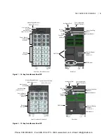
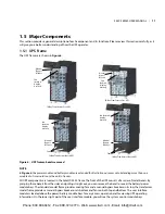
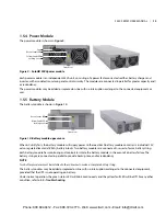
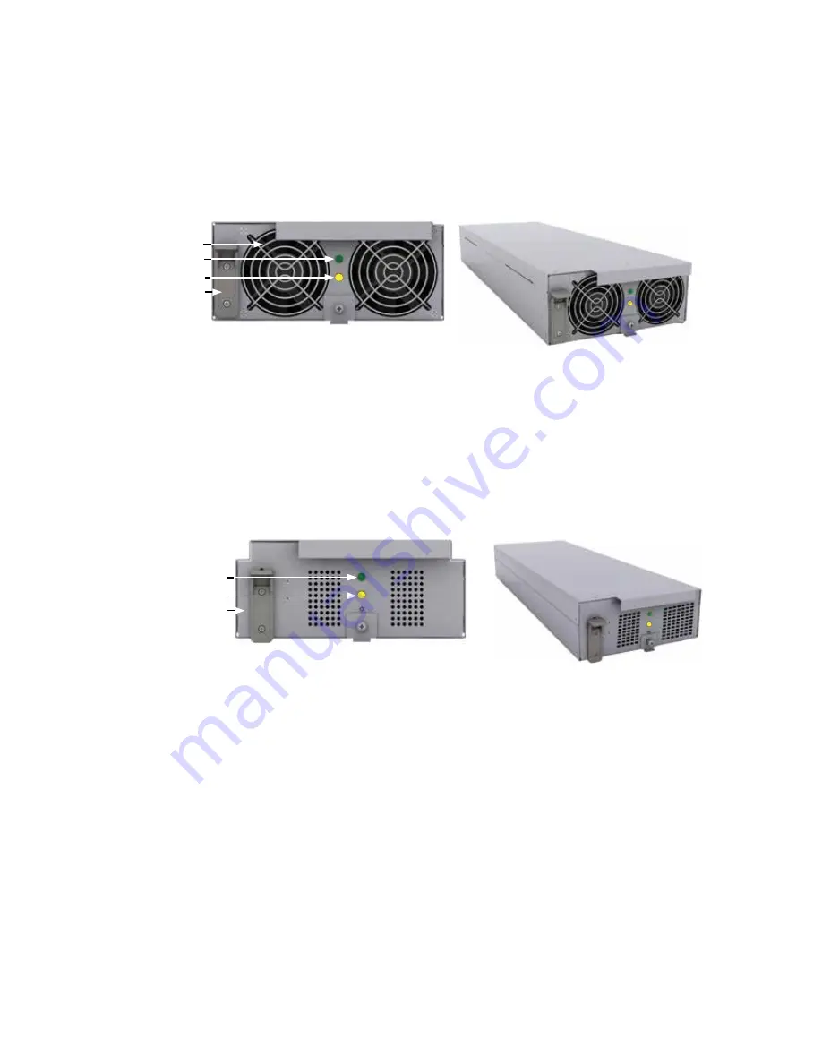
The power module is shown in
Figure 9.
Figure 9: SolaHD S5KC power module
Each power module is an independent 5kVA unit, consisting of a power factor corrected rectifier, battery charger and
inverter, with associated monitoring and control circuitry� The modules are connected in parallel for greater capacity and/
or redundancy�
The power modules may be added or replaced on-line with no interruption or danger to the connected equipment or
user�
1.5.5 Battery Module
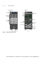
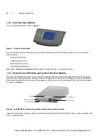
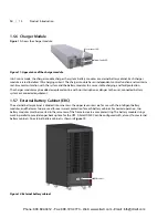
The battery module is shown in
Figure 10.
Figure 10: Battery module appearance
When AC utility fails, the battery module will supply power to the load� Each battery module contains six individual 12V,
valve-regulated lead-acid (VRLA) battery blocks� Two battery modules are connected in series to form a battery string�
Each battery module has monitoring and controls to isolate the battery module in the event of a battery failure� The
battery strings are connected in parallel to provide backup time and/or redundancy�
NOTE
Two battery modules must be installed in the same row to make a complete battery string.
The battery modules may be added or replaced on-line with no interruption or danger to the connected equipment,
provided that the UPS is not operating on battery�
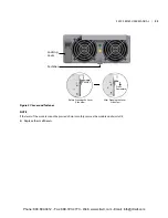
Under normal operation, the green status LED will blink continuously and the yellow fault LED will be Off� For any other
condition, refer to
5.0 - Troubleshooting.
Fan
Green Status LED
Yellow Fault LED
Front View
Locking Lever
Green Status LED
Yellow Fault LED
Front View
Locking Lever
S5KC SERIES USER MANUAL | 13
Phone: 800.894.0412 - Fax: 888.723.4773 - Web: www.clrwtr.com - Email: info@clrwtr.com

