background image

2.5.1  Transformer-Free UPS Cable Connection

A junction box is factory-installed on each model of the SolaHD S5KC to ease cable connection� Select the appropriate 

input cables according to Table 3 and Table 4 based on the UPS rating and mains frequency; however, it is recommended 

that you size the over current protection and wiring for the frame rating to easily allow upgrades to the UPS system�

To connect the cable:
NOTE

Input and output cables must be run in separate conduit before cable connection.

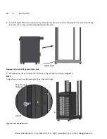
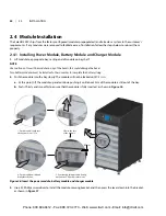
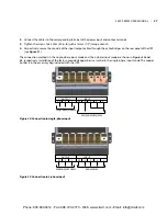
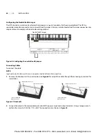
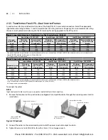
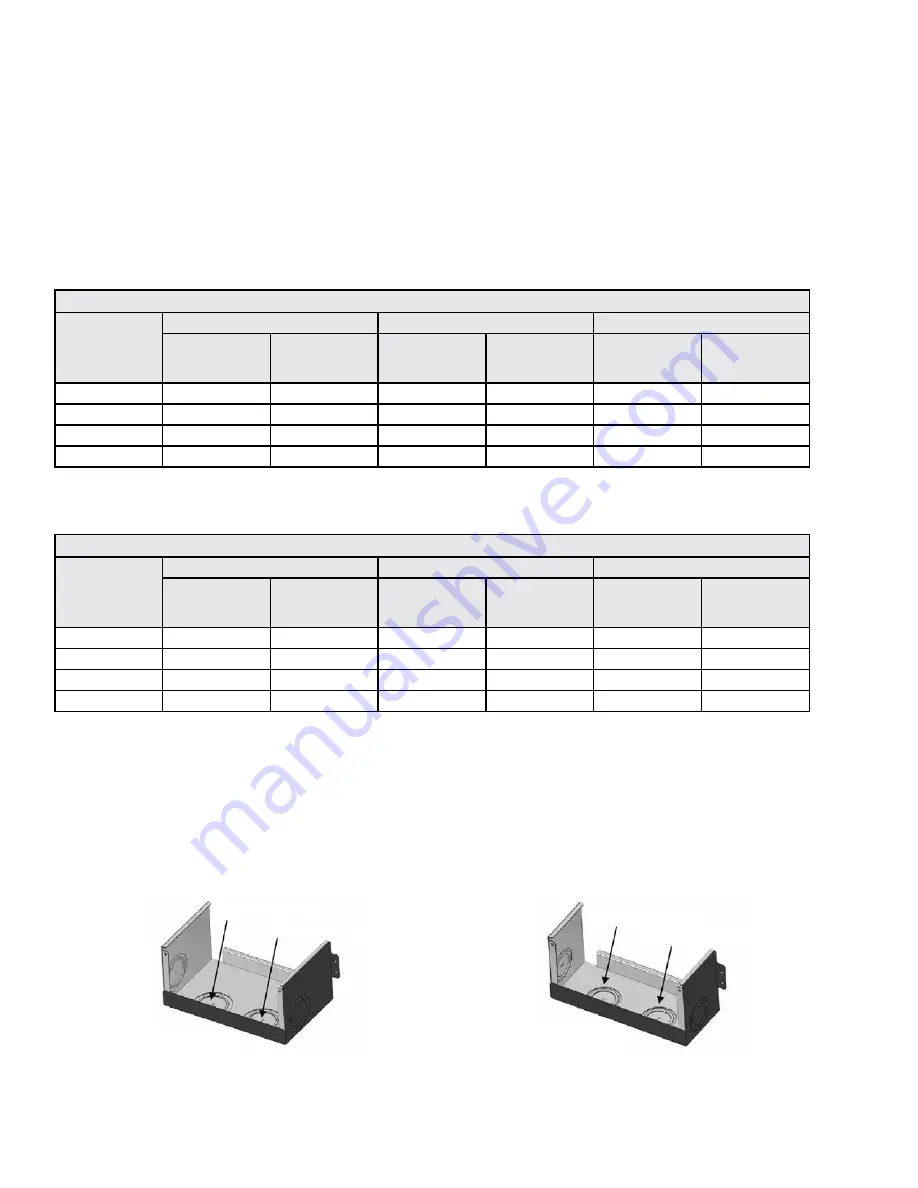
1.  Remove the knockouts at the junction box (see 

Figure 31

) and pull the cables through them, leaving some slack for 

installation�

Figure 31: Knockouts

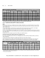
Table 3:  Input cable selection list—60Hz

Maximum System 

Rated Load

Input voltage - 200VAC

Input voltage - 208VAC

Input voltage - 240VAC

Maximum 

Current in UPS 

Mode

Recommended 

Input Protection 

Circuit Breaker

Maximum 

Current in UPS 

Mode

Recommended 

Input Protection 

Circuit Breaker

Maximum 

Current in UPS 

Mode

Recommended 

Input Protection 

Circuit Breaker

5kVA

27A

50A

26A

50A

23A

50A

10kVA

53A

63A

51A

63A

45A

63A

15kVA

80A

100A

77A

100A

67A

100A

20kVA

106A

125A

102A

125A

90A

125A

The power input and output terminals accept a maximum cable cross-sectional area of 35mm2 (2AWG); the minimum cable

cross-sectional area is 16mm2 (6AWG); the rated torque is 4�52Nm (40 in-lb)�

Use of 90°C copper wire is recommended

Table 4:  Input cable selection list—50Hz

Maximum System 

Rated Load

Input Voltage - 220VAC

Input Voltage - 230VAC

Input Voltage - 240VAC

Maximum 

Current in UPS 

Mode

Recommended 

Input Protection 

Circuit Breaker

Maximum 

Current in UPS 

Mode

Recommended 

Input Protection 

Circuit Breaker

Maximum 

Current in UPS 

Mode

Recommended 

Input Protection 

Circuit Breaker

5kVA

25A

50A

24A

50A

23A

50A

10kVA

49A

63A

47A

63A

45A

63A

15kVA

73A

100A

70A

100A

67A

100A

20kVA

97A

125A

93A

125A

90A

125A

The power input and output terminals accept a maximum cable cross-sectional area of 35mm2 (2AWG); the minimum cable cross- sectional area is 

16mm2 (6AWG); the rated torque is 4�52Nm (40 in-lb)�

Use of 90°C copper wire recommended

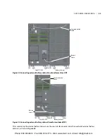
10-Bay SolaHD S5KC 

No Transformer

Output Cable Knockout

Input Cable Knockout

16-Bay SolaHD S5KC 

No Transformer

Output Cable Knockout

Input Cable Knockout

26 | 2�0 

INSTALLATION

Phone: 800.894.0412 - Fax: 888.723.4773 - Web: www.clrwtr.com - Email: info@clrwtr.com

Summary of Contents for S5KC

Page 1: ...S4K2U 5C Series Industrial On Line UPS 230 V 1000 VA 3000 VA User Manual SolaHD S5KC Series User Manual 5 20kVA Modular UPS Phone 800 894 0412 Fax 888 723 4773 Web www clrwtr com Email info clrwtr com...

Page 2: ...ule 14 1 5 7 External Battery Cabinet EBC 14 2 0 INSTALLATION 15 2 1 Unpacking Inspection 15 2 1 1 Installation Environment 15 2 1 2 Installation Tools 15 2 1 3 Installation Site 15 2 2 Unloading the...

Page 3: ...ort 43 4 0 OPERATION AND DISPLAY PANEL 44 4 1 Overview 44 4 2 LCD Screen 46 4 2 1 Startup Screen 46 4 2 2 Main Screen 46 4 2 3 Default Screen Screen Saver 51 4 3 LCD Screen Views 51 4 3 1 AC Mains Scr...

Page 4: ...Battery Run Times 72 7 1 1 Tables for UPS Where Model Number Digits 1 4 are S5KA 72 7 2 Estimated Battery Run Times 75 7 2 1 Tables for UPS Model Number Where Digits 1 4 are S5KB 75 7 3 Estimated Bat...

Page 5: ...leveling feet 17 Figure 17 Installation position and drilling hole dimensions for stationary mounting 17 Figure 18 Install cage nuts 18 Figure 19 Install the tray 18 Figure 20 Install the guide rails...

Page 6: ...gure 46 Pin layout of the dry contacts 40 Figure 47 REPO connector pin layout 41 Figure 48 REPO switch connections 41 Figure 49 Pin layout of the temperature sensor terminal 42 Figure 50 LCD port 43 F...

Page 7: ...ll out a battery module a power module or a charge module 65 Figure 72 Replacing the user interface module 66 Figure 73 Replace clean the top filter 67 Figure 74 Replace clean the bezel filter 68 Figu...

Page 8: ...n definition of the temperature sensor terminal 42 Table 17 LED descriptions 44 Table 18 Audible alarm descriptions 45 Table 19 Control buttons functions 45 Table 20 Function descriptions of menu butt...

Page 9: ...N UPS model number 9 N 81 Table 40 16 bay single phase transformer based unit Type R UPS model number 96 R 82 Table 41 16 bay single phase transformer based unit Type F UPS model number 9 F 83 Table...

Page 10: ...RNING Risk of electric shock Can cause equipment damage injury and death The battery can present a risk of electrical shock and high short circuit current The following precautions should be observed...

Page 11: ...ries Proper disposal of batteries is required Refer to your local laws and regulations for disposal requirements Never block or insert any object into the ventilation holes or other openings DO NOT CO...

Page 12: ...lt the manual Indicates the unit contains a valve regulated lead acid battery Recycle DC voltage Equipment grounding conductor Bonded to ground AC voltage Toggle between On and Off Standby Do not disp...

Page 13: ...continuous high quality AC power to your equipment protecting it from any power disturbance due to blackouts brownouts surges or noise interference The SolaHD S5KC UPS is an easily adaptable UPS syst...

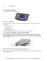
Page 14: ...ker Output Breaker External Battery Cabinet Connector PAD Breakers Rear View USB Port Dry Contacts RS 232 Port Intelligent Card Slots Power Input and Output Terminals System Enabling Breaker Output Br...

Page 15: ...odules Front View Bezels Removed Rear View PAD Port USB Port Dry Contacts RS 232 Port Intelligent Card Slots System Enabling Breaker External Battery Cabinet Connector Input Breaker Power Input and Ou...

Page 16: ...les Front View Bezels Removed Rear View PAD Port USB Port Dry Contacts RS 232 Port Intelligent Card Slots System Enabling Breaker External Battery Cabinet Connector PAD Breakers Input Breaker Power In...

Page 17: ...toring User friendly interface with audible alarms and event logs Supporting hot pluggable and online update Compatible with backup generators Standard Components UPS frame User interface module for c...

Page 18: ...bypass contactor manual bypass output transformer certain frames only and AC output Input EMI Filter Power Module s EMI Filter Output Manual Bypass Battery Module s User Interface Control Interface Sy...

Page 19: ...f the AC utility mains source Auto Restart Mode After a power outage and complete battery discharge and once AC utility is restored the UPS will automatically restart and resume supplying power to con...

Page 20: ...battery power module bays The standard model frame provides cooling fans and a manual bypass breaker on its top the transformer model frame provides a manual bypass breaker on its bottom and fans on...

Page 21: ...monitor module are the communication backbone of the UPS They gather input from all modules and process the data to control the operation of the system including monitoring the condition of each modu...

Page 22: ...blocks Two battery modules are connected in series to form a battery string Each battery module has monitoring and controls to isolate the battery module in the event of a battery failure The battery...

Page 23: ...cted equipment 1 5 7 External Battery Cabinet EBC The external battery cabinet is divided into nine rows the upper seven rows are for use with the intelligent battery modules and the lower two are use...

Page 24: ...mes corrosive gases and liquids 2 1 2 Installation Tools The tools required to properly set up your UPS are listed below Pallet jack 17mm 11 16 wrench or socket 13mm 1 2 wrench or socket 10mm wrench o...

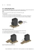
Page 25: ...2 Use a 17mm 11 16 wrench to remove the four mounting bolts from the pallet brackets see Figure 14 3 Remove the mounting brackets from the UPS with a 10mm wrench or socket or a 3 Phillips screwdriver...

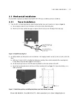
Page 26: ...e unit to the floor a Drill holes 10 3mm 13 32 in the floor for stationary mounting these will accommodate the mounting bolts removed from the pallet Refer Figure 17 for the layout b Use the mounting...

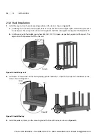
Page 27: ...0U 12U spaces respectively again in all four posts The cage nuts will help secure the UPS in the rack Figure 18 Install cage nuts 2 Install the rack mount shelf on the corresponding position between 1...

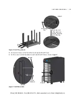
Page 28: ...brackets to each side of the UPS frame as shown in Figure 21 Figure 21 Install the brackets C Guide Rail Insert one end of the guide rail into the mounting slot on the tray Mounting Slot Detail C Bra...

Page 29: ...nto the rack 7 Use eight panel screws to secure the UPS frame to the rack posts as shown in Figure 23 NOTE It might be necessary to use the leveling feet to get the holes to align Figure 23 Fix the UP...

Page 30: ...the metal plate as shown in Figures 24 and 25 Figure 24 Install the metal plate The installation is complete as shown in Figure 25 Figure 25 Installation completed F Detail F Screw 4 places Metal Pla...

Page 31: ...ule into the bay slowly The module will not be locked until 1 3 is in a At this point lift the module up and continue pushing it until about 5cm of the module is still out of the bay b Push it firmly...

Page 32: ...thly remove the module and reinstall it 4 Replace the small bezels Pull Out Press Downward After Pressing the Lever Side View Before Pressing the Lever Side View Locking Lever Fastener S5KC SEries use...

Page 33: ...move the display bezel and the user interface LCD module on top of the frame as shown in Figure 28 Figure 28 Remove large display bezel and user interface module 2 Push the module slowly until about 1...

Page 34: ...tempting to install wiring to this unit This UPS cables should be connected by a properly trained and qualified electrician Refer to the unit model number in Table 2 to determine which instructions to...

Page 35: ...45A 63A 15kVA 80A 100A 77A 100A 67A 100A 20kVA 106A 125A 102A 125A 90A 125A The power input and output terminals accept a maximum cable cross sectional area of 35mm2 2AWG the minimum cable cross sect...

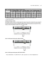
Page 36: ...d the 3 phase input mode are shown in Figures 32 and 33 respectively Installation of the factory provided copper bar is essential in the single phase input mode The copper busbar is in the accessory b...

Page 37: ...on recommends sizing the frame s overcurrent protection and wiring to permit easier UPS system upgrades Table 5 Key to Figures 32 and 33 UPS Wiring System Voltage System Nominal Frequency Input Termin...

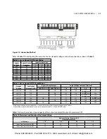
Page 38: ...ransformer based frames 50 Hz Maximum System Rated Load Input Voltage 220VAC Input Voltage 230VAC Input Voltage 240VAC Maximum Current in UPS Mode Recommended Input Protection Circuit Breaker Maximum...

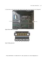
Page 39: ...nduit before cable connection 1 Remove the knockouts at the junction box see Figure 37 and pull the cables through them leaving some slack for installation Figure 37 Knockouts 2 Connect the cable to t...

Page 40: ...tage Between Terminals 208V TAP 1 2 240V TAP 2 3 1 4 3 4 2 3 1 3 200 100 200 OK 100 100 173 Do Not Use 200 220 110 220 OK 110 110 190 Do Not Use 220 230 115 230 OK 115 115 199 Do Not Use 230 220 127 2...

Page 41: ...ction Circuit Breaker 5kVA 28A 50A 27A 50A 27A 50A 10kVA 56A 63A 54A 63A 54A 63A 15kVA 84A 100A 80A 100A 80A 100A 20kVA 112A 125A 107A 125A 107A 125A The power input and output terminals accept a maxi...

Page 42: ...the rear panel of the UPS see Figure 40 Figure 40 Secure cables on cable bridges Figure 41 Wiring connections OUTPUT INPUT PE N L2 L1 PE N L2 L1 Cable Bridge Cable Bridge S5KC SEries user manual 33 Ph...

Page 43: ...tall and tighten the grounding screw on the battery cable assembly on both the UPS and EBC ends This screw also secures the cable assembly to the frames to prevent accidental disconnection 5 For new s...

Page 44: ...the external battery cabinet use the user interface to determine the number of external battery cabinets as shown in Figure 44 Communication Cable Battery Cable Battery Cabinet SolaHD S5KC Battery Ca...

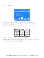
Page 45: ...e SolaHD S5KC UPS provides the capability to add integrated distribution outlets PADs as an option to allow direct AC power connection of the supported equipment to the UPS These PADs are intended to...

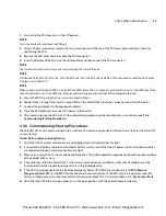
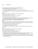
Page 46: ...e manufacturer s instructions see 2 5 6 Commissioning Startup Procedures 2 5 6 Commissioning Startup Procedures The SolaHD S5KC can be commissioned with or without AC power being connected Follow thes...

Page 47: ...PS will shutdown and power will be lost to the connected equipment If the UPS reaches the battery EOD level and shuts down AC mains power must be present to restart the UPS system 1 Check to ensure th...

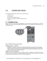
Page 48: ...d instead of the standard card if communication to two third party platforms is required Third party platforms include SNMP and 485 Modbus Bacnet protocols This card would still be used for communicat...

Page 49: ...tput dry contact normally open When the UPS is operating on battery the dry contact is closed upon battery low voltage alarm The maximum voltage and current are 24VDC and 0 3A respectively Any Mode Sh...

Page 50: ...nition Figure 47 REPO connector pin layout Figure 47 shows the schematic diagram of REPO switch connections Figure 48 REPO switch connections WARNING Risk of electrical shock Can cause property damage...

Page 51: ...with external LRT battery systems Pins 13 16 of the contact terminal strip are used to connect a temperature sensor See Figure 49 and Table 16 for the pin definition of the temperature sensor termina...

Page 52: ...et T568B standard type cable can be used Maximum cable length is 14 meters to ensure proper communication signals between the UPS and the LCD module The user interface module provides three network po...

Page 53: ...D On Green The battery is discharging Flashing Green The battery has a pre alarm of low voltage On Red The DC DC converter is faulty Off The battery is charging and the DC DC converter is not function...

Page 54: ...rform relevant function parameter settings and control operations Figure 52 User interface module layout Table 18 Audible Alarm Descriptions Alarm sound Meaning One beep per second When the UPS has an...

Page 55: ...atically according to the currently displayed screen On any screen pressing the F1 button will return to the Output screen System Information Window The system information window displays the current...

Page 56: ...BC Count Number of connected External Battery Cabinets Output L N Voltage V L N Output Voltage L N Current A L N Output Current Frequency Hz Output Frequency Power Factor Output Power Factor Line Volt...

Page 57: ...slot 2 and the serial port on the rear panel cannot work at the same time you must select one of them to work If INTERFACE2 is selected the slot 2 can communicate if RS232 is selected the serial port...

Page 58: ...available for selection Factory default is 8 weeks Auto Batt Test Start Day Sets the day of the week for the automatic battery test Auto Batt Test Start Time Sets the time of the day for the automatic...

Page 59: ...acilitate maintenance Company Name Allows customer service personnel to set the UPS company name to facilitate maintenance Contact Number Allows customer service personnel to set the UPS company conta...

Page 60: ...gives a detailed description of each display screen and its contents The default main screen is the Output menu and its data The navigation indicated for each screen below is in reference to the Outp...

Page 61: ...talled battery modules cumulative discharge time in hours and External battery cabinet count 4 3 3 Output Screen The main screen is the output screen by default as shown in Figure 58 Figure 58 Output...

Page 62: ...en From the main screen press the F4 button twice until the UPS info screen is displayed as shown in Figure 60 Figure 60 UPS info screen The UPS information screen displays UPS ID name set by user ser...

Page 63: ...isplayed as shown in Figure 61 Figure 61 Redundancy screen The redundant screen displays the number of installed power modules in the frame and whether the system contains a redundant module or not 54...

Page 64: ...same method in Step 2 and press the F5 button when complete SolaHD S5KC Series Redundant set Remote comms shutdown Bypass set Output Frequency Output Voltage Sync Range Enabled Disabled Enabled 50Hz...

Page 65: ...ings Screen for entering the password and making changes to the battery setting parameters 4 5 2 Language Selection Screen From the main screen press the F4 button six times until the language screen...

Page 66: ...e and alarm date time stamp 4 5 4 Records Screen From the main screen press the F4 button eight times until the records screen is displayed as shown in Figure 66 Figure 66 Records screen The records s...

Page 67: ...e UPS system needs to alert or remind the user of alarm notifications or require the user to confirm a command or perform other operations When this occurs a prompt window will pop up as shown in Figu...

Page 68: ...relevant setting Short Circuit Recovery After the UPS output short circuits wait 30 seconds before turning On the UPS again System is not ready When the power modules in the frame is initializing or...

Page 69: ...exist contact your local SolaHD service representative Power Module Fan Failure One or more of the power module fans has failed Check to see if the fan is blocked If not contact your local SolaHD serv...

Page 70: ...ystem and the control lever is removed The alarm reminds you to open the startup switch before pulling out the control module Open the startup switch Time to Check the Fan Filters for Excessive Dirt W...

Page 71: ...erature Warning A high temperature condition has occurred in the output transformer area Check the air filters located behind the bezels and clean if necessary or check to see if the ambient temperatu...

Page 72: ...the problem contact your local SolaHD service representative Table 26 Descriptions of Module LEDs Green Status LED Yellow Fault LED Descriptions of Module State Off Off The module is not inserted int...

Page 73: ...le you may need to manually place the UPS into manual bypass before removing modules to avoid accidental loss of output power for the connected equipment 2 The method for removing a module varies depe...

Page 74: ...while the SolaHD S5KC is turned On System Enable switch On and input power available If this module is replaced while the UPS is Off the UPS settings will be reset to factory defaults when the UPS is...

Page 75: ...72 Replacing the user interface module Large Bezel Large Bezel User interface module User interface module 66 5 0 TROUBLESHOOTING Phone 800 894 0412 Fax 888 723 4773 Web www clrwtr com Email info clrw...

Page 76: ...e operating properly Verify redundancy if applicable 6 3 Cleaning Fan Filters The intake fans contain filters that will need to be replaced or cleaned periodically depending on the surrounding environ...

Page 77: ...ter 6 3 3 Bottom Fan Filter Transformer Based Frames Only 1 Remove the three lower bezels at the bottom of the frame 2 Remove the screws and take out the filter as shown in Figure 75 and clean the fil...

Page 78: ...320 145 1 360 163 3 550 249 5 580 263 1 320 145 1 360 163 3 Unit Weight frame rating populated 565 256 3 700 317 5 795 360 6 920 417 3 565 256 3 700 317 5 Shipping Weight frame rating populated 605 2...

Page 79: ...Nominal Voltage 144VDC Recharge Time 5 Hr to 90 capacity PM internal charger with 1 1 ratio of PM to Battery Strings Output Data Output Voltage VAC 200 208 220 230 240 Single Phase 100 100 173 200 11...

Page 80: ...62040 2 Class A FCC Part 15 Class A Safety Standards IEC EN AS 62040 1 2008 UL 1778 4th Ed and CSA 22 2 No 107 3 Immunity Standards IEC EN AS 61000 4 2 3 4 5 6 Transportation ISTA 1E Dimensions WxDxH...

Page 81: ...00 107 120 127 134 140 145 149 153 157 160 164 166 184 191 198 204 210 215 220 225 60 11 20 28 41 48 53 71 81 97 106 113 128 135 142 147 152 157 161 164 167 188 196 203 210 216 222 227 304 309 313 317...

Page 82: ...9 163 165 181 189 195 202 207 213 218 60 11 20 28 40 47 53 70 79 95 104 112 126 133 140 146 151 155 159 163 166 184 192 200 207 213 219 224 301 306 311 50 14 25 37 47 53 72 83 100 110 126 134 142 148...

Page 83: ...80 480 10 78 154 216 327 422 438 449 457 464 480 480 480 480 480 480 480 480 480 480 480 480 480 480 480 480 480 480 480 480 480 480 10 kVA 9 kW 100 5 10 15 20 26 32 39 44 48 52 62 69 75 81 92 99 104...

Page 84: ...9 442 444 447 449 451 453 455 20 44 73 105 132 149 161 186 206 223 308 320 329 337 344 423 428 433 437 441 445 448 451 454 456 458 460 462 464 466 480 480 480 480 480 10 98 143 165 213 311 330 344 427...

Page 85: ...449 20 41 67 98 125 143 156 165 194 212 227 311 321 330 337 344 422 427 432 436 440 443 446 449 452 454 456 459 461 462 464 466 467 480 10 83 135 159 199 227 320 335 347 429 437 443 449 454 458 461 46...

Page 86: ...43 445 447 20 41 67 98 125 143 156 165 194 212 227 311 321 330 337 344 422 427 432 436 440 443 446 449 452 454 456 459 461 462 464 466 467 10 83 135 159 199 227 320 335 347 429 437 443 449 454 458 461...

Page 87: ...125 131 137 142 147 151 155 159 162 165 167 187 193 200 206 211 216 221 226 60 11 20 28 39 47 53 69 79 94 103 111 125 133 139 145 150 155 159 162 166 183 191 199 206 212 218 224 301 305 310 314 318 5...

Page 88: ...163 166 183 190 196 202 208 213 218 60 11 19 27 38 46 52 67 77 91 101 109 123 131 137 143 148 153 157 161 164 167 187 195 202 208 214 220 225 302 307 311 50 14 25 36 46 52 70 81 98 108 122 132 139 146...

Page 89: ...0 10 71 147 203 317 342 431 443 452 459 465 480 480 480 480 480 480 480 480 480 480 480 480 480 480 480 480 480 480 480 480 480 480 10 kVA 9 kW 100 5 10 15 20 26 31 38 43 47 51 60 67 74 79 90 96 102 1...

Page 90: ...37 341 346 422 425 428 432 434 437 440 442 444 446 20 38 61 91 112 137 150 161 182 201 217 302 312 322 330 337 343 421 426 430 434 438 441 445 447 450 452 455 457 459 461 462 464 465 10 75 124 151 167...

Page 91: ...444 446 20 38 61 91 112 137 150 161 182 201 217 302 312 322 330 337 343 421 426 430 434 438 441 445 447 450 452 455 457 459 461 462 464 465 10 75 124 151 167 210 305 322 336 347 427 435 441 446 451 45...

Page 92: ...440 442 444 20 38 61 91 112 137 150 161 182 201 217 302 312 322 330 337 343 421 426 430 434 438 441 445 447 450 452 455 457 459 461 462 464 10 75 124 151 167 210 305 322 336 347 427 435 441 446 451 4...

Page 93: ...120 127 134 139 144 149 153 157 160 163 166 183 191 197 204 209 215 220 225 60 12 21 30 41 48 60 72 81 97 106 120 128 136 142 148 153 157 161 164 180 189 197 204 211 217 222 300 305 309 314 318 50 15...

Page 94: ...166 183 191 197 204 209 215 220 60 11 20 28 40 48 53 71 80 96 105 113 128 135 141 147 152 156 160 164 167 187 195 203 209 216 221 227 304 308 313 50 15 26 38 48 61 74 91 103 112 128 137 144 150 156 16...

Page 95: ...0 10 91 160 301 337 430 444 455 462 480 480 480 480 480 480 480 480 480 480 480 480 480 480 480 480 480 480 480 480 480 480 480 10 kVA 9 kW 100 5 10 16 21 26 32 39 44 48 52 63 70 76 81 93 99 105 109 1...

Page 96: ...99 212 223 305 314 322 328 334 340 345 421 425 429 433 436 439 441 444 446 449 451 453 455 456 20 46 76 108 136 152 164 193 213 301 314 325 334 342 420 426 432 436 440 444 448 451 453 456 458 461 463...

Page 97: ...451 453 454 20 44 73 105 133 149 161 187 207 224 309 320 330 338 345 423 429 433 438 442 445 448 451 454 456 459 461 463 465 466 480 480 480 480 480 10 100 145 167 216 314 333 346 429 438 445 451 456...

Page 98: ...451 20 44 73 105 133 149 161 187 207 224 309 320 330 338 345 423 429 433 438 442 445 448 451 454 456 459 461 463 465 466 480 480 480 10 100 145 167 216 314 333 346 429 438 445 451 456 460 464 467 480...

Page 99: ...Phone 800 894 0412 Fax 888 723 4773 Web www clrwtr com Email info clrwtr com...

Page 100: ...ve been providing a rich tradition of long term practical high quality solutions with applications ranging from the construction and safe operation of petrochemical and process plants to providing qua...

Reviews: