FIGURES
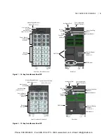
Figure 1 — 16-bay transformer-free UPS � � � � � � � � � � � � � � � � � � � � � � � � � � � � � � � � � � � � 5
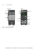
Figure 2 — 10-bay transformer-free UPS � � � � � � � � � � � � � � � � � � � � � � � � � � � � � � � � � � � � 5
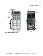
Figure 3 — 12-bay transformer-based UPS � � � � � � � � � � � � � � � � � � � � � � � � � � � � � � � � � � � 6
Figure 4 — 16-bay transformer-based UPS � � � � � � � � � � � � � � � � � � � � � � � � � � � � � � � � � � � 7
Figure 5 — Operating principle diagram � � � � � � � � � � � � � � � � � � � � � � � � � � � � � � � � � � � � 9
Figure 6 — UPS frames, bezels removed � � � � � � � � � � � � � � � � � � � � � � � � � � � � � � � � � � � � 11
Figure 7 — User interface module � � � � � � � � � � � � � � � � � � � � � � � � � � � � � � � � � � � � � � � 12
Figure 8 — SolaHD S5KC system control module and the system monitor module � � � � � � � � � � � � � � � � 12
Figure 9 — SolaHD S5KC power module � � � � � � � � � � � � � � � � � � � � � � � � � � � � � � � � � � � � 13
Figure 10 — Battery module appearance � � � � � � � � � � � � � � � � � � � � � � � � � � � � � � � � � � � � 13
Figure 11 — Appearance of the charger module � � � � � � � � � � � � � � � � � � � � � � � � � � � � � � � � 14
Figure 12 — External battery cabinet� � � � � � � � � � � � � � � � � � � � � � � � � � � � � � � � � � � � � � 14
Figure 13 — Front and rear installation clearances � � � � � � � � � � � � � � � � � � � � � � � � � � � � � � � 15
Figure 14 — Remove the mounting brackets � � � � � � � � � � � � � � � � � � � � � � � � � � � � � � � � � � 16
Figure 15 — Connect the ramp and remove UPS � � � � � � � � � � � � � � � � � � � � � � � � � � � � � � � � 16
Figure 16 — Adjust the leveling feet � � � � � � � � � � � � � � � � � � � � � � � � � � � � � � � � � � � � � � 17
Figure 17 — Installation position and drilling hole dimensions for stationary mounting � � � � � � � � � � � � � 17
Figure 18 — Install cage nuts � � � � � � � � � � � � � � � � � � � � � � � � � � � � � � � � � � � � � � � � � 18
Figure 19 — Install the tray � � � � � � � � � � � � � � � � � � � � � � � � � � � � � � � � � � � � � � � � � � 18
Figure 20 — Install the guide rails � � � � � � � � � � � � � � � � � � � � � � � � � � � � � � � � � � � � � � � 19
Figure 21 — Install the brackets � � � � � � � � � � � � � � � � � � � � � � � � � � � � � � � � � � � � � � � � 19
Figure 22 — Push the UPS frame into the rack � � � � � � � � � � � � � � � � � � � � � � � � � � � � � � � � � 20
Figure 23 — Fix the UPS frame � � � � � � � � � � � � � � � � � � � � � � � � � � � � � � � � � � � � � � � � � 20
Figure 24 — Install the metal plate � � � � � � � � � � � � � � � � � � � � � � � � � � � � � � � � � � � � � � � 21
Figure 25 — Installation completed � � � � � � � � � � � � � � � � � � � � � � � � � � � � � � � � � � � � � � 21
Figure 26 — Insert the power module, battery module and charger module � � � � � � � � � � � � � � � � � � � 22
Figure 27 — Lever and fastener � � � � � � � � � � � � � � � � � � � � � � � � � � � � � � � � � � � � � � � � 23
Figure 28 — Remove large display bezel and user interface module � � � � � � � � � � � � � � � � � � � � � � � 24
Figure 29 — Insert the System Control and System Monitor module � � � � � � � � � � � � � � � � � � � � � � � 24
Figure 30 — Lever and fastener on System Control and System Monitor Module � � � � � � � � � � � � � � � � � 25
Figure 31 — Knockouts � � � � � � � � � � � � � � � � � � � � � � � � � � � � � � � � � � � � � � � � � � � � 26
Figure 32 — Connection in single-phase input � � � � � � � � � � � � � � � � � � � � � � � � � � � � � � � � � 27
S5KC MBC SERIES USER MANUAL | v
Phone: 800.894.0412 - Fax: 888.723.4773 - Web: www.clrwtr.com - Email: info@clrwtr.com


