background image


15

CABLE INSTALLATION

Wiring Preparation

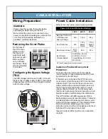
Removing the Cover Plates

On the back of 
the UPS, cover 
plates are over 
the input and 
output terminals, 
as shown at right. 
Remove these 
using a Phillips 
screwdriver. Keep 
screws and plates 
to one side.

Configuring the Bypass Voltage 

(TB2)

The UPS voltage is factory-set to 208 V. Should 
the user have a utility supply of 240 V, the bypass 
voltage jumper will have to be changed to ensure 
correct output voltage.

Power Cable Installation

Refer to the chart below when selecting cables

Customer-Provided Overcurrent 

Protection

A branch rated overcurrent protection device 
(circuit breaker or fused disconnect switch) must 
be installed for the AC input.
If the start-up is on bypass, the UPS has a six-
cycle inrush current that is up to 20 times the rated 
output current. This must be taken into account 
when selecting the overload protection device at 
the AC input supply distribution point. To avoid 
random tripping on start up, it is recommended 
that the AC input supply be protected with a circuit 
breaker capable of withstanding this initial inrush.
This UPS is fitted with EMI suppression filters. 
Earth leakage current is less than 40mA. Transient 
and steady state earth leakage currents may occur 
when starting the equipment. This should be taken 
into account when selecting ground current 
detection devices, as the earth leakage currents of 
both the UPS and load will be carried.
Input and output cables must be run in separate 
conduits.

WARNING:

Please read this section thoroughly before 
attempting to install wiring to this unit.
Be sure that the unit is not connected to any 
power source before installing any wiring to this 
unit. This UPS should be installed by a 
qualified / certified electrician.

Remove Cover Plates

208 V

(default)

240 V

OR

Bypass Voltage Jumper

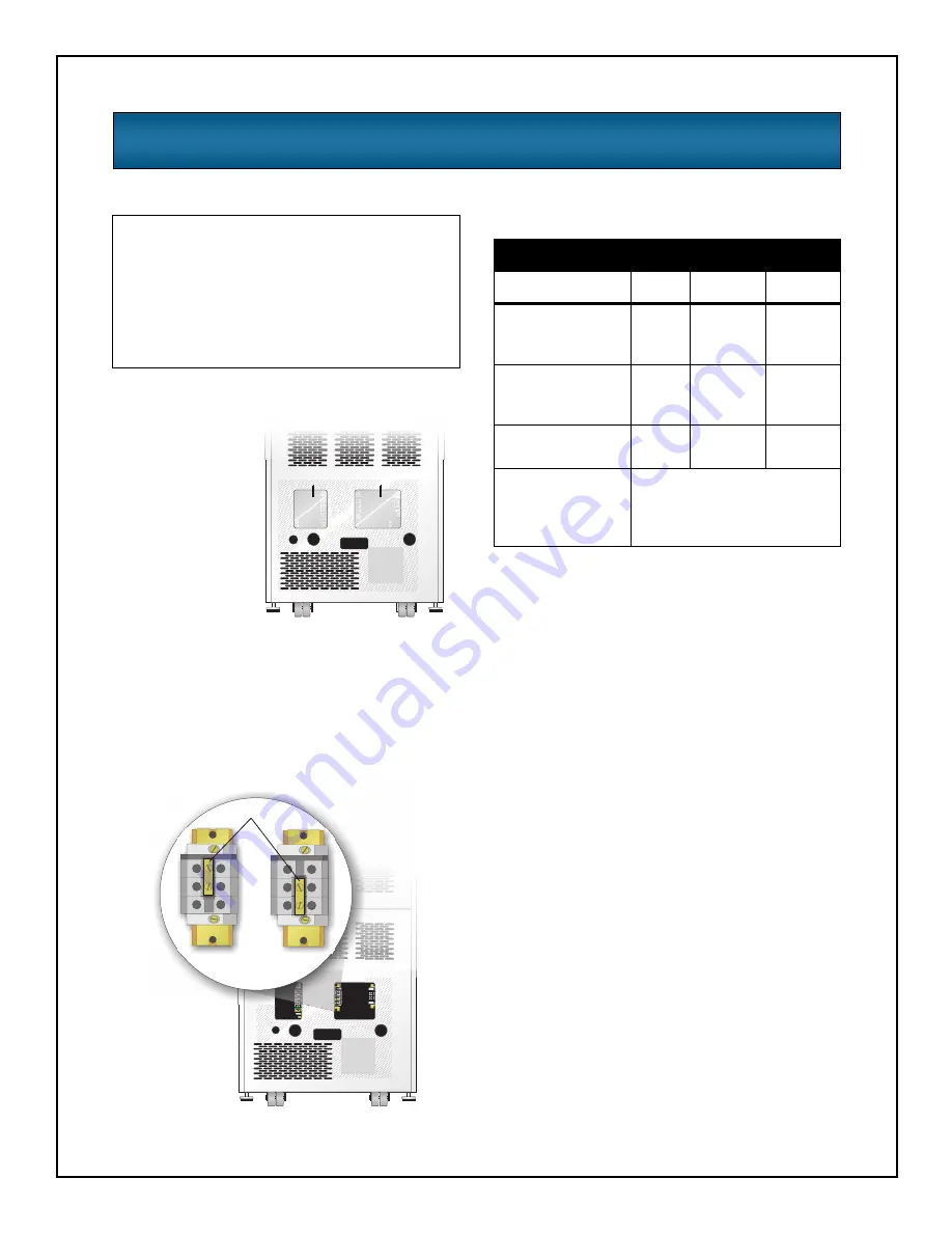
Power Cable and Protection Ratings

120 V

208 V

240 V

Max Input Current in
 UPS Mode and
Nominal Voltage

N/A

102 A

88 A

Input Protection

N/A

125 A

Branch

Rated

125 A

Branch

 Rated

Max Output Current

83 A/

phase

96 A

83 A

Input/Output
Terminal Details

2 AWG Max: 35 mm²
6 AWG Min: 16 mm²
Torque Rating: 2.5-3.0 Nm
(22-26 in-lb)

90°C rated copper wire is recommended

Summary of Contents for S5K

Page 1: ...S5K Modular UPS USER MANUAL 208 240V 60Hz 12 to 20 kVA...

Page 2: ......

Page 3: ...m Control Module 8 Power Module 9 Battery Module 9 Installation 11 PREPARATION 12 Inspection 12 Environment 12 Required Setup Equipment 12 Site Preparation 12 UNLOADING 13 Unloading the UPS 13 Station...

Page 4: ...ration Settings 27 Change Settings Menu 27 UPS Configuration Screen Service Mode Menu 31 Display Date Time 31 Event Log 32 Alarm Log 32 Transfer to Bypass 32 Module Replacement 33 Tools 34 Troubleshoo...

Page 5: ...by qualified personnel Electromagnetic Compatibility The S5K Modular UPS complies with the limits for a Class A digital device pursuant to Part 15 of FCC rules These limits provide reasonable protecti...

Page 6: ...tput Requests the user to consult the manual Indicates the unit contains a valve regulated lead acid battery Recycle DC voltage Equipment grounding conductor Bonded to ground AC voltage OFF ON Standby...

Page 7: ...3 Introduction General Description Modes of Operation Major Components...

Page 8: ...d to provide maximum system availability to business critical equipment The S5K Modular UPS is also an easily adaptable UPS system By simply installing additional Power or Battery Modules you can expa...

Page 9: ...Battery Module Bays Manual Bypass Switch SW1 Intake Cooling Fans DB 9 Communication Ports Output Power Terminal Input Power Terminal External Battery Connection REPO Terminal Intellislot Communicatio...

Page 10: ...the factory but can be disabled by the user The user can also program two auto restart delay settings 1 Battery capacity level 2 Countdown timer Recharge Mode When AC utility is restored the unit will...

Page 11: ...nd pulling out you will remove the bezel to reveal the Battery Power Module bays the bottom bezel covers the cooling fans and the manual bypass switch The User Interface Module is located above the Po...

Page 12: ...ystem Control Module The System Control Module is the communications backbone of the UPS It gathers input from all modules and processes the data to control the operation of the system including monit...

Page 13: ...ty failure Each module contains 10 individual 12 volt valve regulated VRLA battery blocks with associated monitoring and controls to isolate the Battery Module in the event of a battery failure The mo...

Page 14: ...10...

Page 15: ...11 Installation Preparation Unloading Cable Installation Communications...

Page 16: ...ch in lb Flathead screwdriver 2 Phillips screwdriver Site Preparation When deciding where to locate your UPS consider the weight and size of the unit Make sure that the structural integrity of the flo...

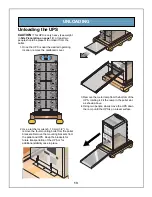
Page 17: ...ver 2 Use a ratchet or wrench 13 mm 1 2 to remove the four mounting bolts from the pallet brackets Remove the mounting brackets from the pallet and UPS Keep the brackets for future transportation of t...

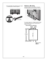
Page 18: ...stability can be added by bolting the mounting brackets used in shipping to the floor For greater stability use a higher grade bolt Refer to the dimensions below when drilling holes for stationary mo...

Page 19: ...that the AC input supply be protected with a circuit breaker capable of withstanding this initial inrush This UPS is fitted with EMI suppression filters Earth leakage current is less than 40mA Transie...

Page 20: ...must be green with or without one or more yellow stripes and is to be installed as part of the branch circuit that supplies the unit or system The grounding conductor is to be grounded to earth at the...

Page 21: ...d 1 2 3 4 5 L L N G 240 VAC 120 VAC 120 VAC UPS Output TB3 Panel Board Input 1 2 3 4 5 L L G 208 VAC UPS Output TB3 Panel Board Input 1 2 3 4 5 L3 L2 L1 N G 208 VAC L1 to L2 120 VAC N to L3 only UPS...

Page 22: ...the S5K Modular UPS Intellislot SNMP cards allows the S5K Modular to communicate intelligently with your Ethernet network The SNMP card must be installed in port 1 any additional cards can be added i...

Page 23: ...19 Operating Instructions Controls and Indicators Operating Procedures Main Menu...

Page 24: ...e occurrence when an LED is lit LCD Display Window Standby Button Alarm Silence Button Fault Warning LED Status LEDs Navigation Buttons ESC Navigates cursor on display menus Returns to previous displa...

Page 25: ...d and Output is On On Battery Operation UPS is On Utility is Good and Output is Off UPS is On Utility is Bad and Output is Off UPS is in Bypass Operation Manual or Automatic UPS is in Manual Bypass Op...

Page 26: ...y pointing up or down as shown below indicating to scroll using the or buttons If you are scrolling through any of the Main Menus items will scroll one line at a time with the menu heading on the top...

Page 27: ...ly transfer the UPS to bypass by operating the manual bypass switch located behind the lowest front cover to the bypass position To transfer the UPS from bypass to normal mode follow the on screen ins...

Page 28: ...olts Amps kVA UPS Frequency UPS Information Module Information Module Replacement Module Replacement Ctrl w Redundant Ctrl w o Redundant Pwr w Redundant Pwr w o Redundant Battery Module Event Log Even...

Page 29: ...x x Output kW xx x Output pf xx x Redundant Status Redundant Status PMs Installed xx PM N 1 redundant non redundant SC Redundant non redundant Battery Status Battery Status Voltage VDC xxx Capacity xx...

Page 30: ...Auto Restart UPS Shutdown Delay Remote Shutdown External Battery Bypass Alarm Mode Intelli Battery Ca Air Filter Reminder Battery Settings Battery Settings Test intrvl 2 weeks on Wed at 06 00 Low Batt...

Page 31: ...of the S5K Modular UPS It can be up to seven characters in length Once set the password will be required to change the configuration NOTE If the password is lost call Sola Hevi Duty Technical Support...

Page 32: ...d the time will automatically adjust to Daylight Saving Time Start Time Start Time 06 00 Auto Battery Test Interval Start Day Start Time Interval Batt Test Interval 1 week 2 weeks 3 weeks 4 weeks 6 we...

Page 33: ...unications Enter the following when using the External Battery Cabinets with Chargers P N PB10SLF105WC120 Bypass Alarm Mode Allows the user to enable disable alarm indicating that the bypass is not qu...

Page 34: ...inder to check the air filters Factory Defaults Allows the user to reset all settings to the values in effect when the UPS was shipped from the factory Air Filter Reminder 2 weeks 4 weeks 10 weeks 26...

Page 35: ...me This feature shows the current date and time At the Main Menu select UPS Configuration and press Next select Display Date Time and press Main Menu UPS Status UPS Configuration Display Date Time Eve...

Page 36: ...umber listed on the back of this manual Alarm Log Alarms affecting the S5K Modular UPS can be viewed at the Alarm Log screen To access the screen go to the Main Menu select Event Log and press When an...

Page 37: ...er 4 Loosen fastener 5 Replace module 6 Tighten fastener 7 Close lever 8 Replace all bezels Control Module w o Redundant Cntl Mod Replacement 1 Remove bottom bezel and place UPS in bypass 2 Lift off d...

Page 38: ...Allows the user to reset the UPS after a Battery Module failure alarm Tools Tools UPS test Clear failures Main Menu UPS Status UPS Configuration Display Date Time Event Log Alarm Log Transfer to Bypas...

Page 39: ...35 Troubleshooting Alarm Messages Module LED Indication Module Replacement...

Page 40: ...larm The UPS is no longer redundant Insert more Power Modules or replace faulty Power Module to regain redundancy Output Off Output Short Circuit There was a short circuit on the output Investigate fa...

Page 41: ...le Not Ready A Battery Module is not ready and should be blinking it s yellow LED Ensure module is fully seated and locked into place Refer to Module LED indication section for corrective action Power...

Page 42: ...complete Wait 30 seconds for alarm to clear Power Module Is Not Ready Please Wait The UPS s output could not be turned on because the Power Module initialization is not yet complete Wait 30 seconds fo...

Page 43: ...n start up qualification mode or module warning FLASHING ON Module failed is off line and module control is functioning OFF FLASHING Abnormal operation re insert module If this persists contact Sola H...

Page 44: ...nterclockwise until it is loosened 4 Start to pull out module About 2 3 out it will stop Slide module away from the center of the UPS Continue to pull until module is removed seen at right 5 Dispose o...

Page 45: ...5 If UPS was placed in bypass manually transfer back to UPS operation 6 Replace bezels Replacing the User Interface 1 Lift off user interface and set it on top of the UPS frame 2 The attached cable wi...

Page 46: ...42...

Page 47: ...43 Maintenance Proper Care Scheduled Maintenance Replacing Fan Filters...

Page 48: ...recommended the following maintenance is performed annually Verify all Power Modules are operating properly Verify all Battery Modules are operating properly Verify redundancy if applicable Replacing...

Page 49: ...45 Reference Specifications Battery Run Times Warranty...

Page 50: ...tage range shall be vari able based upon output loading percentages UPS Load Input Voltage 80 100 170 VAC 60 80 144 VAC 30 60 127 VAC 0 30 110 VAC Power factor Cos 98 Input frequency nominal Hz 60 Inp...

Page 51: ...26 34 85 149 215 283 355 12 000 8400 7 12 16 20 24 28 32 36 90 157 226 298 373 11 500 8050 7 12 17 21 25 29 34 38 95 166 239 314 392 11 000 7700 7 12 17 21 26 30 35 40 101 176 252 332 413 10 500 7350...

Page 52: ...nutes and based on resistive loading at an ambient temperature of 25 C for non redundant standard configurations Backup times for External Battery Cabinets with Chargers do not include internal batter...

Page 53: ...ther to products with removed or altered serial numbers or to any losses or damages due to act of God or source external to the product misuse accident abuse neglect negligence unauthorized modificati...

Page 54: ...50...

Page 55: ......

Page 56: ...use of this information or for any errors or omissions 2002 Sola Hevi Duty All rights reserved throughout the world Specifications subject to change without notice Sola Hevi Duty name and logo are reg...

Reviews: